Vol. 23
Latest Volume
All Volumes
PIERC 150 [2024] PIERC 149 [2024] PIERC 148 [2024] PIERC 147 [2024] PIERC 146 [2024] PIERC 145 [2024] PIERC 144 [2024] PIERC 143 [2024] PIERC 142 [2024] PIERC 141 [2024] PIERC 140 [2024] PIERC 139 [2024] PIERC 138 [2023] PIERC 137 [2023] PIERC 136 [2023] PIERC 135 [2023] PIERC 134 [2023] PIERC 133 [2023] PIERC 132 [2023] PIERC 131 [2023] PIERC 130 [2023] PIERC 129 [2023] PIERC 128 [2023] PIERC 127 [2022] PIERC 126 [2022] PIERC 125 [2022] PIERC 124 [2022] PIERC 123 [2022] PIERC 122 [2022] PIERC 121 [2022] PIERC 120 [2022] PIERC 119 [2022] PIERC 118 [2022] PIERC 117 [2021] PIERC 116 [2021] PIERC 115 [2021] PIERC 114 [2021] PIERC 113 [2021] PIERC 112 [2021] PIERC 111 [2021] PIERC 110 [2021] PIERC 109 [2021] PIERC 108 [2021] PIERC 107 [2021] PIERC 106 [2020] PIERC 105 [2020] PIERC 104 [2020] PIERC 103 [2020] PIERC 102 [2020] PIERC 101 [2020] PIERC 100 [2020] PIERC 99 [2020] PIERC 98 [2020] PIERC 97 [2019] PIERC 96 [2019] PIERC 95 [2019] PIERC 94 [2019] PIERC 93 [2019] PIERC 92 [2019] PIERC 91 [2019] PIERC 90 [2019] PIERC 89 [2019] PIERC 88 [2018] PIERC 87 [2018] PIERC 86 [2018] PIERC 85 [2018] PIERC 84 [2018] PIERC 83 [2018] PIERC 82 [2018] PIERC 81 [2018] PIERC 80 [2018] PIERC 79 [2017] PIERC 78 [2017] PIERC 77 [2017] PIERC 76 [2017] PIERC 75 [2017] PIERC 74 [2017] PIERC 73 [2017] PIERC 72 [2017] PIERC 71 [2017] PIERC 70 [2016] PIERC 69 [2016] PIERC 68 [2016] PIERC 67 [2016] PIERC 66 [2016] PIERC 65 [2016] PIERC 64 [2016] PIERC 63 [2016] PIERC 62 [2016] PIERC 61 [2016] PIERC 60 [2015] PIERC 59 [2015] PIERC 58 [2015] PIERC 57 [2015] PIERC 56 [2015] PIERC 55 [2014] PIERC 54 [2014] PIERC 53 [2014] PIERC 52 [2014] PIERC 51 [2014] PIERC 50 [2014] PIERC 49 [2014] PIERC 48 [2014] PIERC 47 [2014] PIERC 46 [2014] PIERC 45 [2013] PIERC 44 [2013] PIERC 43 [2013] PIERC 42 [2013] PIERC 41 [2013] PIERC 40 [2013] PIERC 39 [2013] PIERC 38 [2013] PIERC 37 [2013] PIERC 36 [2013] PIERC 35 [2013] PIERC 34 [2013] PIERC 33 [2012] PIERC 32 [2012] PIERC 31 [2012] PIERC 30 [2012] PIERC 29 [2012] PIERC 28 [2012] PIERC 27 [2012] PIERC 26 [2012] PIERC 25 [2012] PIERC 24 [2011] PIERC 23 [2011] PIERC 22 [2011] PIERC 21 [2011] PIERC 20 [2011] PIERC 19 [2011] PIERC 18 [2011] PIERC 17 [2010] PIERC 16 [2010] PIERC 15 [2010] PIERC 14 [2010] PIERC 13 [2010] PIERC 12 [2010] PIERC 11 [2009] PIERC 10 [2009] PIERC 9 [2009] PIERC 8 [2009] PIERC 7 [2009] PIERC 6 [2009] PIERC 5 [2008] PIERC 4 [2008] PIERC 3 [2008] PIERC 2 [2008] PIERC 1 [2008]
2011-09-02
PIER C
Vol. 23, 265-275, 2011
download: 283
Design of Tri-Band Printed Monopole Antenna for WLAN and WiMAX Applications
Jia Chen , Shou-Tao Fan , Wei Hu and Chang-Hong Liang
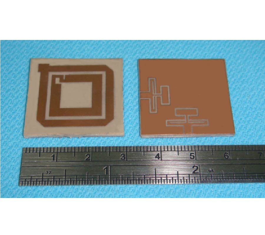
A novel printed monopole antenna with a pair of parasitic patches for wideband operation is proposed and studied. With the use of parasitic patches along the microstrip feed line, a good performance of bandwidth enhancement is obtained. The measured impedance bandwidth, defined by voltage standing wave ratio (VSWR) ≤ 2, can operate from 2.3 to 6.2 GHz. A tri-band printed monopole antenna is created by introducing two notched bands in the wideband antenna. Etching an n-shaped slot on the radiating element and embedding a U-shaped parasitic strip on the bottom, two notched bands from 2.78 to 3.34 GHz and from 3.78 to 5.1 GHz are achieved. The measured impedance bandwidths of the tri-band antenna are 410 MHz (2.37-2.78 GHz), 440 MHz (3.34-3.78 GHz) and 1000 MHz (5.1-6.1 GHz), which can meet the bandwidth requirements of 2.4/5.2/5.8 GHz wireless local area network (WLAN) and 2.5/3.5/5.5 GHz worldwide interoperability for microwave access (WiMAX) standards. In addition, the proposed antennas have good omnidirectional radiation characteristics and stable gains over the whole operating bands.
DESIGN OF TRI-BAND PRINTED MONOPOLE ANTENNA FOR WLAN AND WIMAX APPLICATIONS
2011-09-01
PIER C
Vol. 23, 249-263, 2011
download: 299
Variable Coupling Ratio Y-Branch Plastic Optical Fiber (POF) Coupler with Suspended Waveguide Taper
Abang Annuar Ehsan , Sahbudin Shaari and Mohd Kamil Abd-Rahman
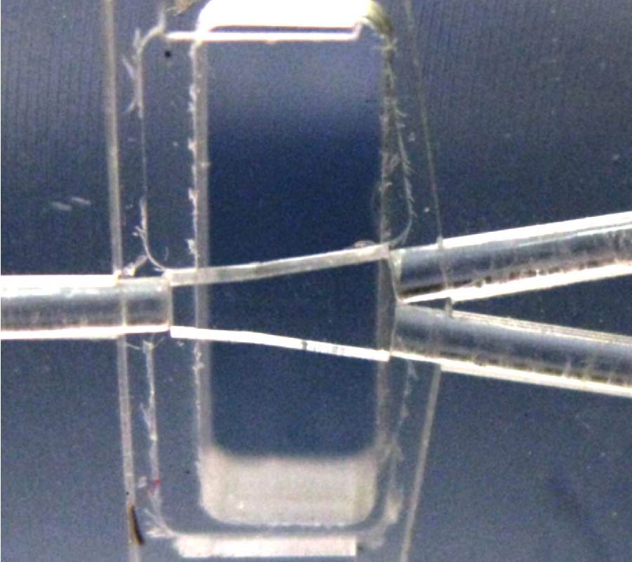
A variable coupling ratio Y-Branch plastic optical fiber (POF) coupler based on acrylic has been developed. This device utilized two optical designs: a Y-branch structure with a novel suspended waveguide taper and a simple attenuation technique based on lateral displacement of two fibers for the non-symmetrical coupling ratios. The high index contrast waveguide taper is constructed on the acrylic block itself where the area surrounding the waveguide taper has been designed in such a way that it is surrounded by an open air. A simple attenuation technique based on lateral displacement of two adjoining fibers for each of the two output ports has been proposed and presented for the non-symmetrical coupling ratios. Lateral displacement of the fiber is set from 4.4 mm down to 1.6 mm for output fiber 1 and 0.1 mm to 1.0 mm for output port 2. Numerical analysis has been done on the lateral displacement of the output fibers which shows the device is able to generate non-symmetrical coupling ratios. Device modeling has been performed using non-sequential ray tracing technique on the Y-branch coupler performing as a 3 dB coupler with an excess loss of 1.84 dB and a coupling ratio of 50:50. The designed coupling ratios vary from 1% to 45% for port 1 and 99% down to 55% for port 2 whereas in the simulated device, ratios vary from 7.65% to 39.85% for port 1 and from 92.35% down to 60.15% for port 2. Fabrication of the device is done by producing the device structures on an acrylic block using high speed CNC machining tool. The fabricated device has an excess loss of 5.85 dB while the coupling ratios are 56.86% and 43.14% when operating as a 3 dB coupler. In the variable coupling ratio mode, the coupling ratios are 10.09% to 32.88% for port 1 and 89.91% down to 67.12% for port 2. The excess loss of the fabricated device varies from 5.85 dB to 8.49 dB.
VARIABLE COUPLING RATIO Y-BRANCH PLASTIC OPTICAL FIBER (POF) COUPLER WITH SUSPENDED WAVEGUIDE TAPER
2011-08-31
PIER C
Vol. 23, 233-247, 2011
download: 364
Tunable Band-Pass Filter Using RF MEMS Capacitance and Transmission Line
Shimul Chandra Saha , Ulrik Hanke , Hakon Sagberg , Tor A. Fjeldly and Trond Saether
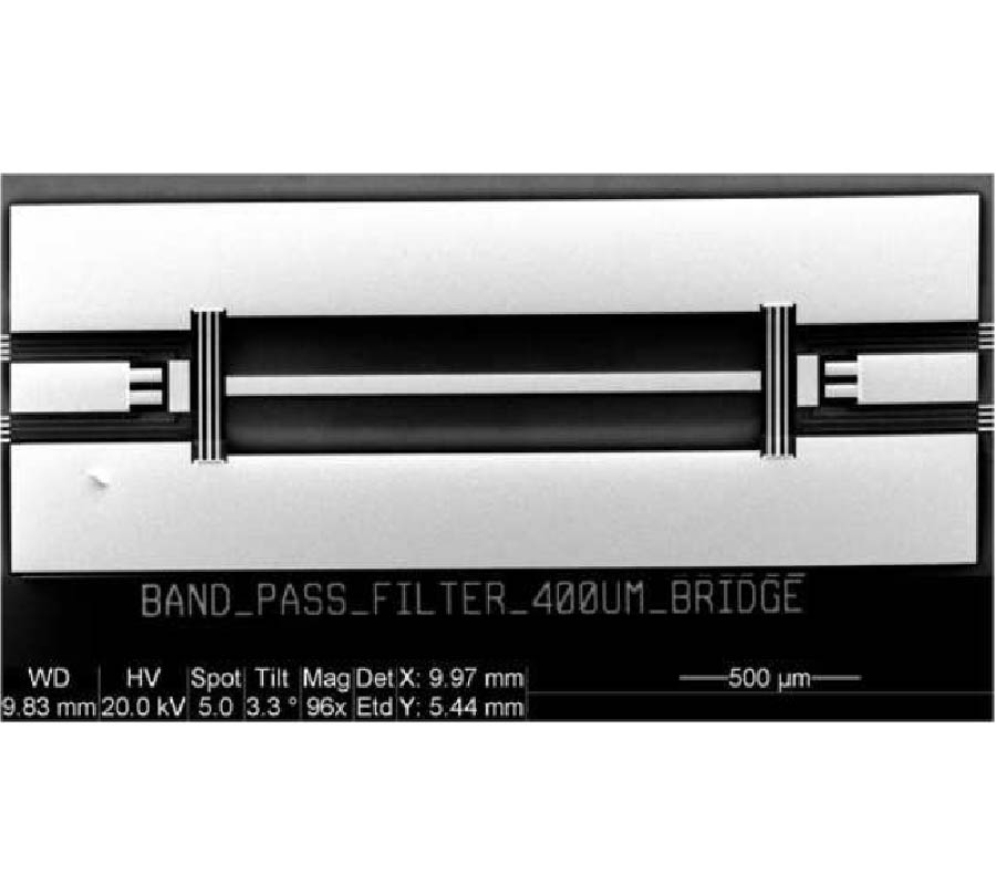
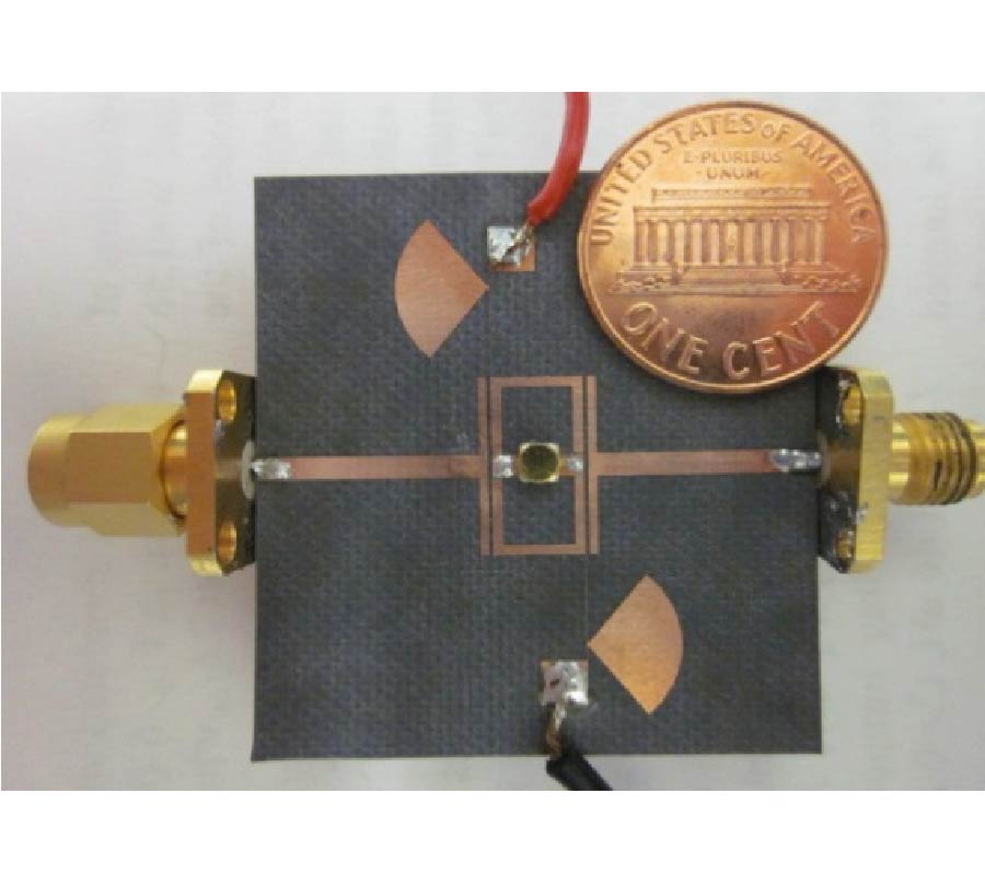
In this paper we present the design and fabrication of an RF MEMS tunable band-pass filter. The band-pass filter design uses both distributed transmission lines and RF MEMS capacitances together to replace the lumped elements. The use of RF MEMS variable capacitances gives the flexibility of tuning both the centre frequency and the band-width of the band-pass filter. A prototype of the tunable band-pass filter is realized using parallel plate capacitances. The variable shunt and series capacitances are formed by a combination of parallel plate RF MEMS shunt bridges and series cantilevers. The filter operates at C-X band. The measurement results agree well with the simulation results.
TUNABLE BAND-PASS FILTER USING RF MEMS CAPACITANCE AND TRANSMISSION LINE
2011-08-30
PIER C
Vol. 23, 219-231, 2011
download: 330
Feasibility Study of Antenna Integrated Capacitive Sensor in Operational Mobile Phone
Sami Myllymaki , Arttu Huttunen , Vamsi Krishna Palukuru , Heli Jantunen , Markus Berg and Erkki T. Salonen
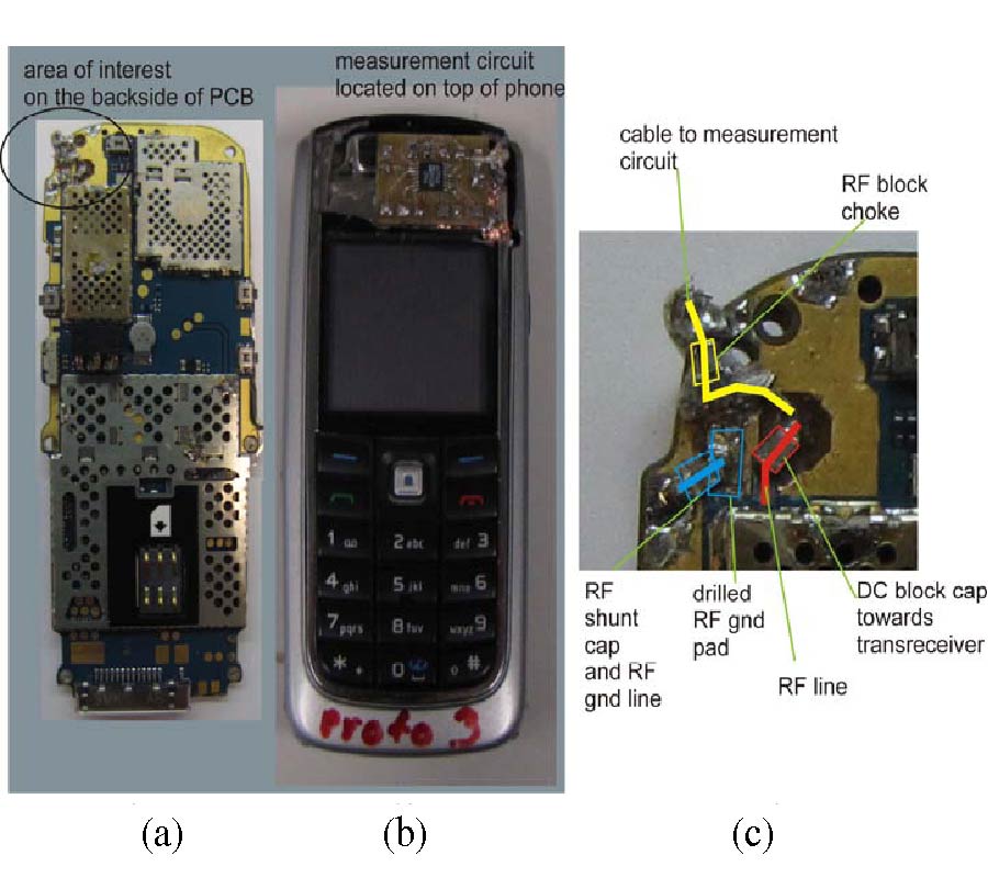
An antenna integrated sensor implementation for hand or finger proximity recognition is developed. Capacitive sensor was installed on the antenna of functional Nokia 6021 phone. The sensitivity of the phone with planar inverted F antenna (PIFA) integrated sensor was measured with active TRP (total radiated power) and TIS (total isotropic sensitivity) measurements. Phone active measurements were performed with/without data cables and compared to reference phones. Passive cable phone measurements were compared with active measurement results. TRP results had no significant decrements due to integration compared with the reference phone. Some TIS channels suffered from detrimental effects due to interfering signals, which were measured with a spectrum analyzer.
FEASIBILITY STUDY OF ANTENNA INTEGRATED CAPACITIVE SENSOR IN OPERATIONAL MOBILE PHONE
2011-08-16
PIER C
Vol. 23, 205-217, 2011
download: 294
Fractal-Shaped Complementary Electric-LC Resonator for Bandstop Filter
He-Xiu Xu , Guang-Ming Wang and Qing Peng
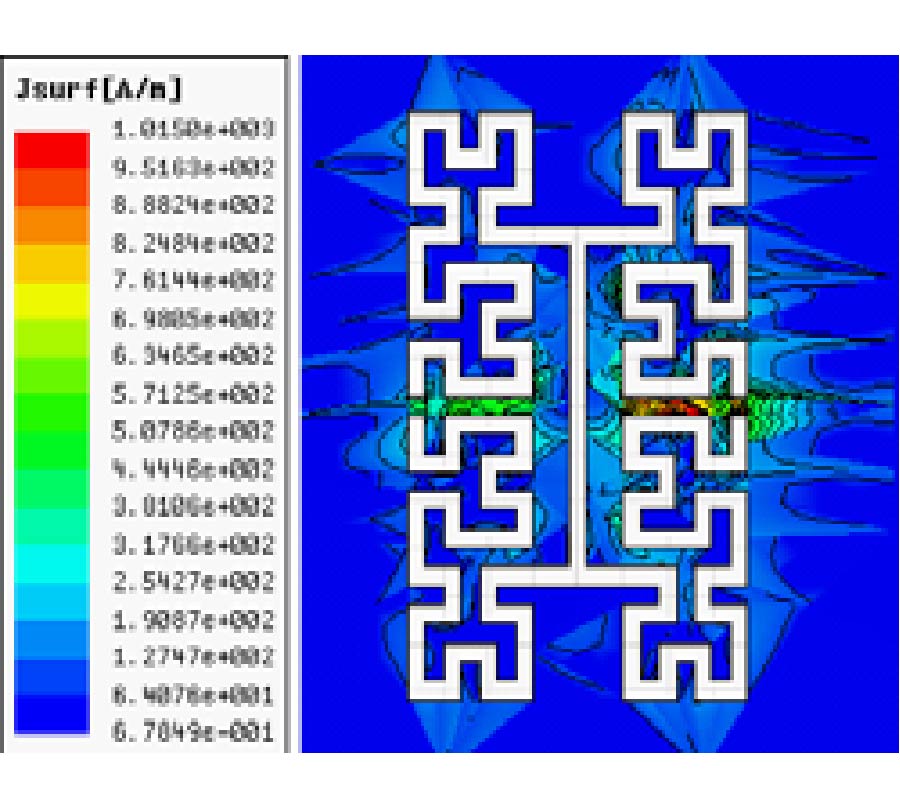
An equivalent circuit model for single negative metamaterial (MTM) transmission line based on microstrip complementary electric inductive-capacitive resonator (CELC) is proposed for the first time. The verified circuit model gives strong support to the interpretation of all exhibited electromagnetic (EM) phenomena. The nonpure magnetic and electric resonances have been demonstrated by constitutive EM parameters. Based on the conclusions that have drawn, a more compact sub-wavelength particle based on Hilbert-shaped CELC (H-CELC) is proposed. The design procedures of the H-CELC-loaded MTM cell are derived based on the circuit model. For application, a bandstop filter covering one of the ISM bands 5.2 GHz by cascading two H-CELC cells is designed, fabricated and measured. Consistent results between simulation and measurement have confirmed the design. The established theory based on the proposed circuit model is of reference value for the design of novel bandstop devices.
FRACTAL-SHAPED COMPLEMENTARY ELECTRIC-LC RESONATOR FOR BANDSTOP FILTER
2011-08-16
PIER C
Vol. 23, 191-203, 2011
download: 279
Design of Novel CPW Cross-Fed Antenna
Shu Lin , Guan-Long Huang , Run-Nan Cai , Xue-Ying Zhang and Xing-Qi Zhang
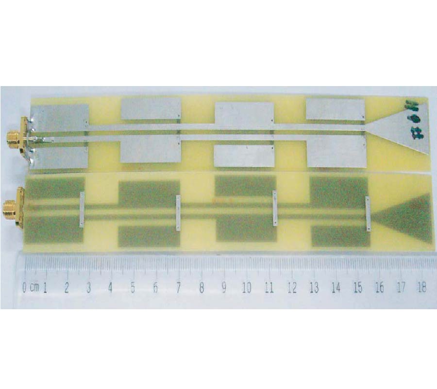
A novel coplannar waveguide (CPW) cross-fed antenna which is wideband, high-gain and omnidirectional is proposed. After simulating the antenna model by CST MICROWAVE STUDIO®, the results show that this antenna not only has compact size, but also can effectively broaden operating band, improve gain and remain omnidirectional. In addition, adjusting antenna elements' dimension and spacing can control the central frequency position of operating band and bandwidth. The simulated results of antenna surface currents can be used to explain the reason of antenna possessing broadband and omnidirectional high-gain characteristics. A CPW cross-fed antenna operating at 2.4 GHz is designed and manufactured for measurement. The prototype is printed on a FR-4 epoxy resin board with 1 mm thickness. The experimental results indicate that the operating band is 2.35-2.85 GHz with reflection coefficient less than -10 dB (relative bandwidth 19.2%), and maximum gain in H-plane can achieve 5.2 dBi. Measured results well match the simulated ones. Moreover, the total antenna size is 187 mm × 22.5 mm (1.5λ×0.18λ), which can make it suitable in WLAN systems.
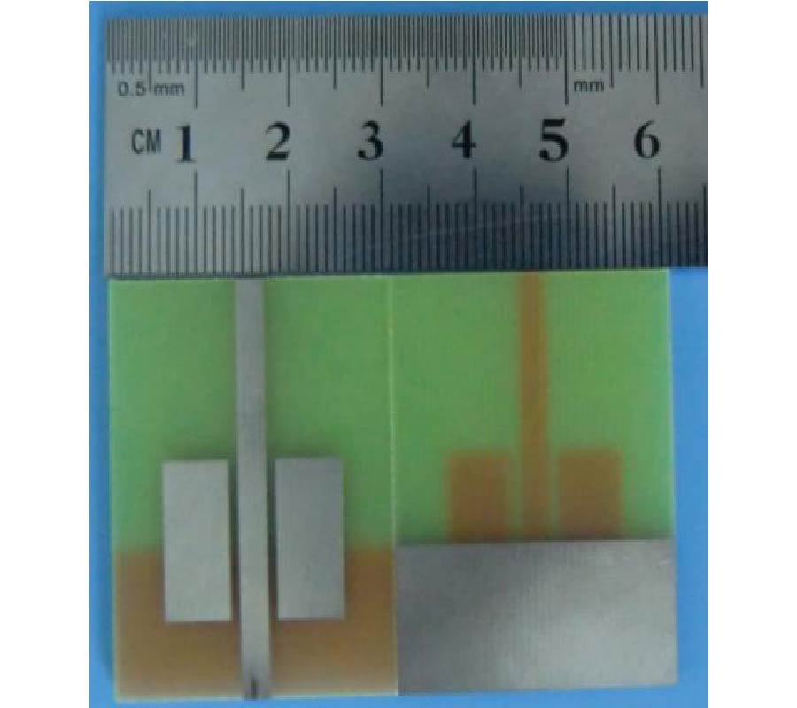
DESIGN OF NOVEL CPW CROSS-FED ANTENNA
2011-08-16
PIER C
Vol. 23, 175-190, 2011
download: 310
SiGe Hbt Dual-Conversion Weaver-Hartley Downconverters with High Image Rejection
Jin-Siang Syu , Chinchun Meng , Sheng-Wen Yu and Ya-Hui Teng
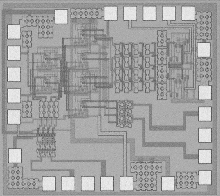
2.4/5.7-GHz dual-band Weaver-Hartley dual-conversion downconverters are demonstrated using 0.35-μm SiGe heterojunction bipolar transistor (HBT) technology with/without a correlated local oscillator (LO) generator. In the first implementation, the correlated LO generator consists of a divide-by-two frequency divider, a frequency doubler and a single-sideband upconverter and thus LO1(=2.5×LO2) signal is generated. As a result, the downconverter with the correlated LO signals has over 39 dB image-rejection ratios for the first/second image signals (IRR1/IRR2) of the dual-conversion system at both 2.4/5.7-GHz modes while the downconverter without the correlated LO generators has a 6-dB higher conversion gain and IRR1/IRR2 of more than 44 dB with the same dc power consumption (excluding the LO generator). On the other hand, a 10-GHz Weaver-Hartley downconverter is demonstrated with a resonant LC load at the first-stage mixer to improve the conversion gain at high frequencies. The downconverter achieves a conversion gain of 8 dB with IRR1/IRR2 better than 43/40 dB.
SIGE HBT DUAL-CONVERSION WEAVER-HARTLEY DOWNCONVERTERS WITH HIGH IMAGE REJECTION
2011-08-16
PIER C
Vol. 23, 161-173, 2011
download: 569
A Novel Ka-Band Solid-State Power Combining Amplifier
Li Zhao , Jun Xu , Lei Wang and Mao-Yan Wang
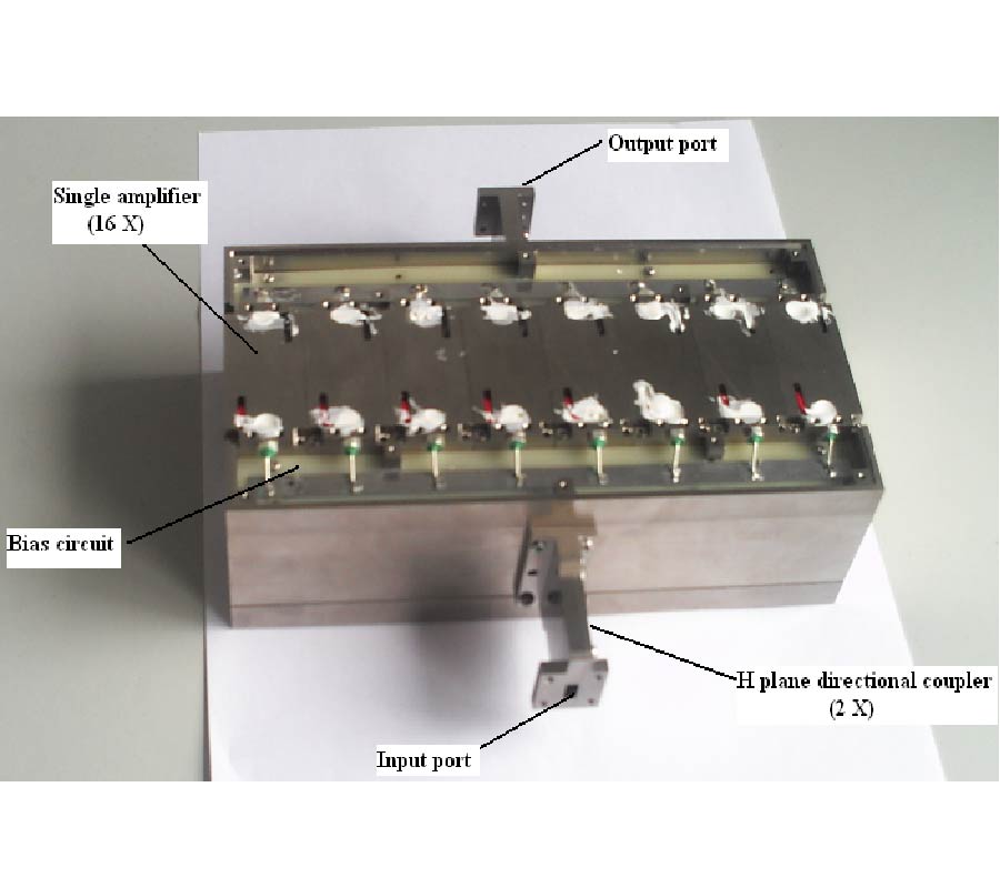
This paper presents a high-efficiency Ka-band solid-state power combining amplifier on the basis of a novel waveguide magic tee. By employing 16 low-power amplifier modules and compact waveguide power combining network with a low loss microstrip-to-waveguide transition, the output loss of the combining circuit is minimized, so a high combining efficiency larger than 85% from 34 to 36 GHz is obtained. Modular architecture is adopted in the combiner design. The single amplifier, bias circuit and heat sink are all fabricated separately, which add great flexibility to the system. Modular amplifiers can be premade and reserved in case any malfunctioning amplifier needs to be replaced. In addition, the improved power combining amplifier has the advantages of low loss, high isolation, compact structure, excellent heat-sink, etc.
A NOVEL KA-BAND SOLID-STATE POWER COMBINING AMPLIFIER
2011-08-15
PIER C
Vol. 23, 151-160, 2011
download: 316
Dual-Mode Split Microstrip Resonator for Compact Narrowband Bandpass Filters
Vladimir V. Tyurnev and Alexey Mikhailovich Serzhantov
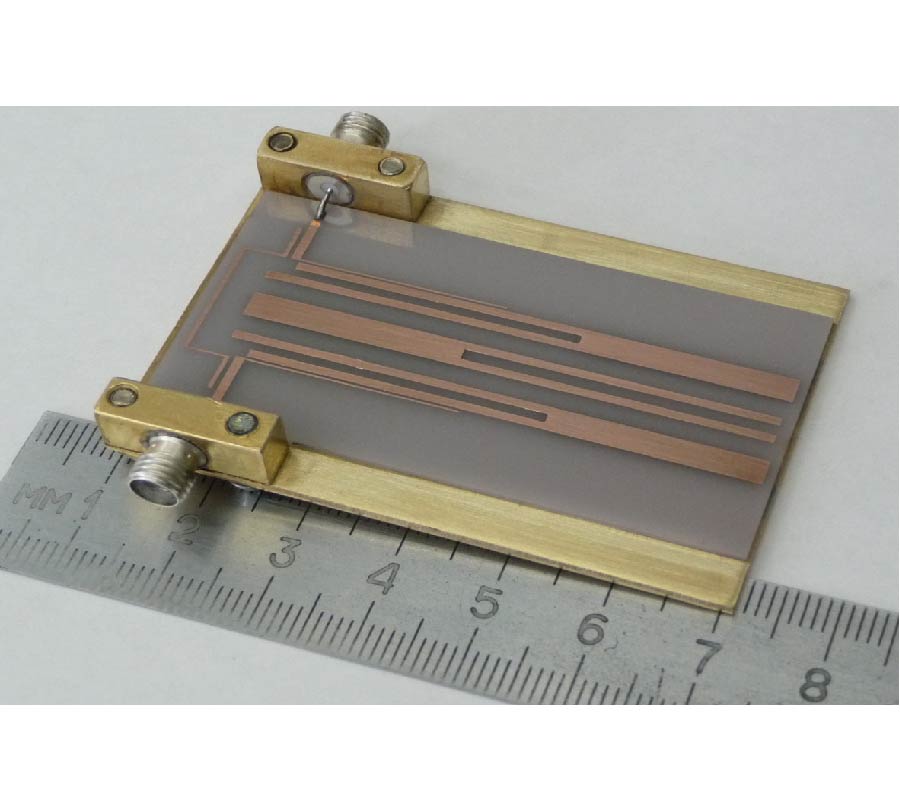
A straight split dual-mode microstrip resonator is proposed. The frequencies of the two first oscillation modes in the resonator may be brought closer together by adjusting a split parameter whereas the frequency of the third mode remains approximately equal to the doubled average frequency of the first and the second modes. It is shown that formulas derived within 1D model give qualitatively true relations between the resonant frequencies and the structure parameters of the resonator. Examples of narrowband bandpass filters of the fourth and the sixth order are described. Transmission zeros below and above the passband substantially improve the filter's performance. The simulated frequency response of the three-resonator dual-mode filter is compared with the measured response of the fabricated filter.
DUAL-MODE SPLIT MICROSTRIP RESONATOR FOR COMPACT NARROWBAND BANDPASS FILTERS
2011-08-12
PIER C
Vol. 23, 137-150, 2011
download: 305
Accurate Modeling of Microstrip Dumbbell Shaped Slot Resoantor (Dssr) for Miniaturized Tunable Resoantor and Band-Pass Filter
Dong-Jin Jung and Kai Chang
In this paper, a novel dumbbell shaped slot resonator (DSSR) is introduced and investigated based on a circuit theory and electromagnetic (EM) simulation. Lumped and distributed equivalent circuit models are then presented for an analysis of the proposed DSSR. The circuit and EM simulated results validate the DSSR's equivalent circuit models and their analysis methodologies. Since the proposed DSSR does not employ ground slots, additional etching process for the ground plane is not necessary. Thus, one can minimize the cost and fabrication errors. For the DSSR's applications, the miniaturized tunable DSSR and band-pass filter (BPF) are designed, simulated, and measured. The tunable DSSR does not require additional lumped DC-block capacitors since DC is isolated due to the coupled gap structures in an input and output. In the BPF design, two DSSRs are simply coupled by input/output ports. Both simulated and measured results of the designed tunable resonator and BPF show good agreement.
ACCURATE MODELING OF MICROSTRIP DUMBBELL SHAPED SLOT RESOANTOR (DSSR) FOR MINIATURIZED TUNABLE RESOANTOR AND BAND-PASS FILTER
2011-08-09
PIER C
Vol. 23, 123-135, 2011
download: 325
3D FEM Modeling and Technology of Piezoelectric Ring MEMS Antenna
Alessandro Massaro , Roberto Cingolani and Adriana Passaseo
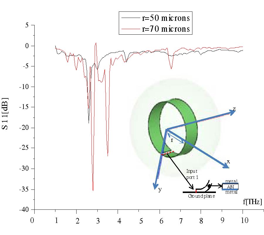
Actually MEMS technology allows to fabricate free standing and bended cantilevers by acting on stress/strain properties and thicknesses of materials. In particular, by means of MEMS technology it is possible to realize ring or spiral layouts with piezoelectric materials. The mechanical movement due to the piezoelectric resonance can be used in order to modulate a signal travelling in the MEMS and radiating in the free space as happens in antennas. In this work we provide an accurate study regarding the design approach of piezoelectric aluminium nitride (AlN) ring antenna. The study is developed by means of a tailored 3D FEM tool which allows to analyze the piezoelectric resonances and to design the ring micro-antenna in the THz range. Finally we provide the technology and we measure the piezoelectric resonances of ring antennas.
3D FEM MODELING AND TECHNOLOGY OF PIEZOELECTRIC RING MEMS ANTENNA
2011-08-07
PIER C
Vol. 23, 111-122, 2011
download: 268
Maximum Likelihood Estimation of Co-Channel Multicomponent Polynomial Phase Signals Using Importance Sampling
Hao Cheng , Deguo Zeng , Jun Zhu and Bin Tang
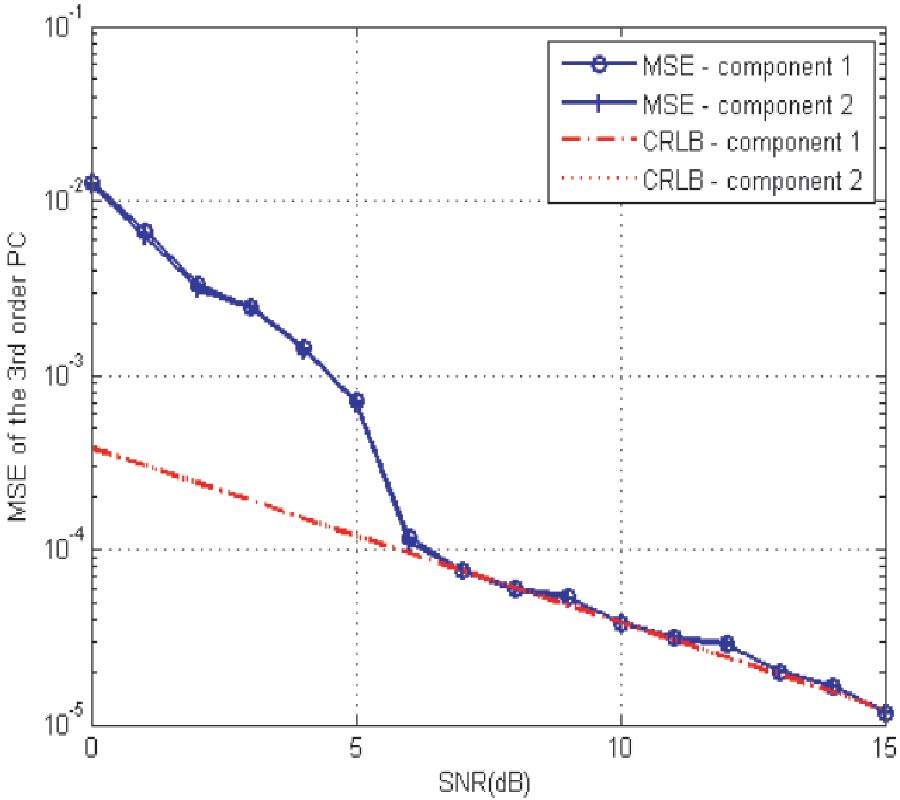
Unlike some traditional polynomial phase signal (PPS) parameter estimation methods restricted to monocomponent case, this paper focuses on the parameter estimation of multicomponent PPSs mixed in a single channel, which is more sophisticated and always involves the cross-term issue. In this investigation, based on the model of multicomponent PPSs in additional white Gaussian noise, we partition the maximum likelihood estimation into two consecutive steps. The first one involving estimation of polynomial coefficients is intensively studied using importance sampling, while the second one involving the estimation of amplitude and initial phase is trivial. Numerical experiments show satisfactory estimation performance even if the parameters are closely spaced.
MAXIMUM LIKELIHOOD ESTIMATION OF CO-CHANNEL MULTICOMPONENT POLYNOMIAL PHASE SIGNALS USING IMPORTANCE SAMPLING
2011-08-04
PIER C
Vol. 23, 95-109, 2011
download: 284
LTCC Fold-Back Bandpass Filter Designed with Capacitively Loaded Stubs
Kuo-Sheng Chin , Jian-Luen Hung , Chun-Wei Huang , Shu-Peng Huang , Yung-An Kao and Shuh-Han Chao
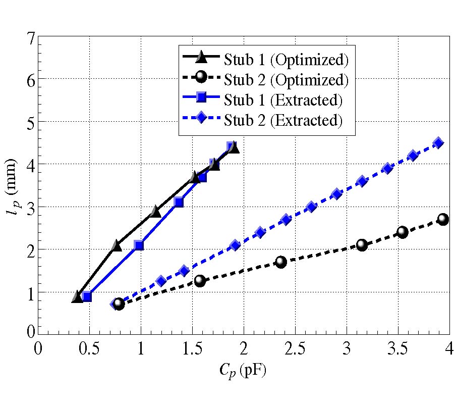
This study presents a design of a compact stub-type bandpass filter with capacitively loaded stubs and a fold-back structure. This paper employed the fabrication process of low-temperature co-fired ceramic (LTCC) for filter realization of a multi-layer structure. The proposed filter structure required adding end capacitors to stubs to extend their electrical length, while achieving a length reduction of 30%. This study provided design curves to determine the dimensions of the end capacitor for reaching maximum electrical length extension. In addition, a fold-back configuration was applied to halve the filter size. An experimental filter operating at 5.8 GHz was fabricated and measured to validate the design concept, achieving a highly compact size of 14.3×8.2×0.76 mm3.
LTCC FOLD-BACK BANDPASS FILTER DESIGNED WITH CAPACITIVELY LOADED STUBS
2011-08-03
PIER C
Vol. 23, 83-93, 2011
download: 279
Dual-Mode CPW-Fed Double Square-Loop Resonators for WLAN and WiMAX Tri-Band Design
Chin-Yen Liu , Bing-Hao Zeng , Ji-Chyun Liu , Chih-Chiang Chen and Dau-Chyrh Chang
An improved CPW-fed configurations with dual-mode double-square-ring resonators (DMDSRR) for tri-band application is proposed in this paper. The resonant frequency equations related to DMDSRR geometry are introduced for simply designing tri-band bandpass filter (BPF). Resonant frequencies and transmission zeroes can be controlled by tuning the perimeter ratio of the square rings. To obtain lower insertion loss, higher out-of-band rejection level and wider bandwidth of tri-band, the improved coplanar waveguide (CPW) fed and the step impedance resonator (SIR) and meander line dual-mode perturbations are designed. The effective design procedure is provided. The proposed filter is successfully simulated and measured. It can be applied to WLAN (2.45, 5.20 and 5.80 GHz) and WiMAX (3.50 GHz) systems.
DUAL-MODE CPW-FED DOUBLE SQUARE-LOOP RESONATORS FOR WLAN AND WIMAX TRI-BAND DESIGN
2011-08-03
PIER C
Vol. 23, 69-81, 2011
download: 364
Parameter Estimation of LFM Signal Intercepted by Synchronous Nyquist Folding Receiver
Deguo Zeng , Hao Cheng , Jun Zhu and Bin Tang
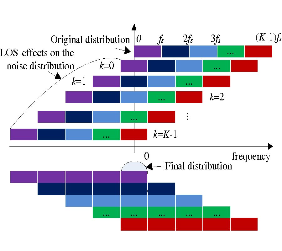
Nyquist folding receiver (NYFR) is a new kind of interception architecture, which can simultaneously intercept wideband signals in multi-Nyquist zones with one or two analog-to-digital converters (ADCs). A parameter estimation algorithm of the linear frequency modulated (LFM) signal intercepted by an improved NYFR is presented. Firstly, the NYFR is improved by introducing a synchronous mechanism, and we denote this structure as a synchronous NYFR (SNYFR). Secondly, taking LFM as an example, the input and output noise distributions of an SNYFR are discussed. Then, a fast parameter estimation algorithm is derived from the frequency spectrum of the output signal, and an advice for the design of local oscillator signal is given. Simulations show that the parameter estimation accuracy is close to the maximum likelihood when the signal to noise ratio (SNR) is above -3 dB.
PARAMETER ESTIMATION OF LFM SIGNAL INTERCEPTED BY SYNCHRONOUS NYQUIST FOLDING RECEIVER
2011-07-29
PIER C
Vol. 23, 55-67, 2011
download: 270
Design of Multiband UWB Filter Based on Reflected Characteristics in Time Domain
VU Ngoc Minh Trang and Yvan Duroc
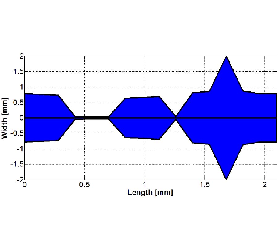
An automatic process to design a multiband filter in Non-uniform Transmission Line (NTL) form is presented. The proposed approach supports with Time Domain Reflectometry (TDR) technique instead of the traditional methods such as methods based on Inductor-Capacitor filters. The proposed method is described step-by-step and is illustrated by an example emphasizing key points. A critical analysis of this technique is done for emphasizing its limitations. For illustrating the design process, a multiband Ultra Wideband (UWB) filter rejecting two frequency bands is designed.
DESIGN OF MULTIBAND UWB FILTER BASED ON REFLECTED CHARACTERISTICS IN TIME DOMAIN
2011-07-28
PIER C
Vol. 23, 41-54, 2011
download: 328
Balanced Mixers Using Wideband Symmetric Offset Stack Balun in 0.18 um CMOS
Hwann-Kaeo Chiou and Jui-Yi Lin
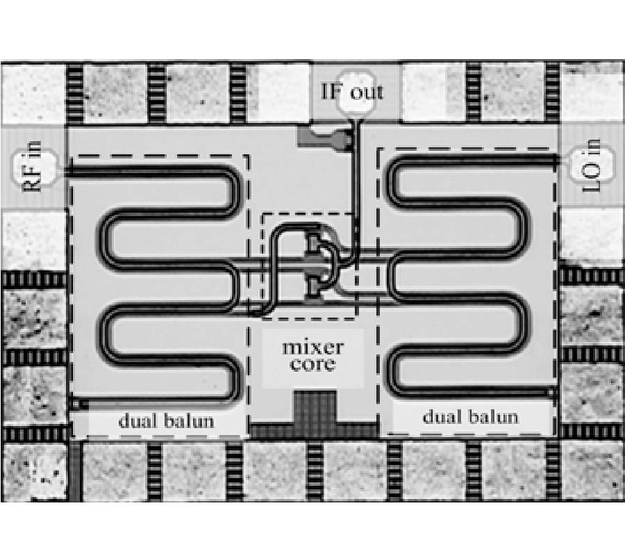
This work proposes a symmetrical offset stack coupled lines balun and a dual balun for a single balanced mixer and a star mixer, respectively. To achieve a minimum insertion loss and a maximum bandwidth, the design formulas are derived by properly selecting the width of coupled lines and the offset width between two coupled lines. The measured results of the proposed single and dual baluns achieve the bandwidths of over 110% and 90%, and insertion losses of less than 4.4 dB and 7.4 dB at 38 GHz. These two baluns occupied chip sizes of 0.07 mm2. Two balanced diode mixers are further proposed and implemented in tsmcTM 0.18-μm CMOS processes. These mixers utilize a stack balun feature wide bandwidth with very compact size. The measured results of the single balanced and star mixer achieve over 115% and 100% bandwidth for a conversion loss of <15 dB. The isolations are better than 24 dB from 10 to 65 GHz of the single balance mixer and better than 31 dB from 20 to 65 GHz of the star mixer.
BALANCED MIXERS USING WIDEBAND SYMMETRIC OFFSET STACK BALUN IN 0.18 UM CMOS
2011-07-28
PIER C
Vol. 23, 27-39, 2011
download: 288
Dual Frequency Ring Antennas with Coplanar Capacitive Feed
Veeresh G. Kasabegoudar
In this paper, design of a coplanar capaciπtive coupled probe fed microstrip ring antenna for dual frequency operation is presented. The proposed antenna is excited by a single probe feed connected to a capacitive feed strip placed along one of the radiating edges of the ring antenna. The coplanar capacitive feed strip is modified to obtain the best possible match with the antenna input impedance and to tune out the excessive capacitive reactance due to feed strip. It is also demonstrated that the modified feed strip can be placed either inside or outside the ring and similar radiation characteristics can be obtained at both the resonant frequencies. Ring dimensions decide the resonant frequencies values and their separation. Measured data fairly agree with the simulated characteristics.
DUAL FREQUENCY RING ANTENNAS WITH COPLANAR CAPACITIVE FEED
2011-07-23
PIER C
Vol. 23, 15-25, 2011
download: 386
High Gain Axial-Mode Helical Antenna with Circular Metal Disk
Shu Lin , Li-Na Wang , Wen Bin Zhang , Chang-Fei Zhou , Xing-Qi Zhang and Jin-Xiang Wang
A method to improve the gain of axial-mode helical antenna is proposed. This method involves a parasitical circular metal disk, which is installed on the front of general axial-mode helical antenna and is apart from the helical line. A circular current whose phase lags behind that of helical line current appears, which brings a more concentrated radiation field. Consequently, the antenna gain is improved. Based on the simulation results, an antenna array model fed independently is proposed. This model gives an excellent explanation of the radiation characteristic of helical antenna. Both the simulation and experiment results show that for obtaining the same gain, the antenna length in this new method is only 71% of that in traditional helical antenna. The reduction of antenna length favors the miniaturization of antenna. In addition, this method has little effect on the bandwidth of antenna, so it can be widely used in the design of helical antenna element and array.
HIGH GAIN AXIAL-MODE HELICAL ANTENNA WITH CIRCULAR METAL DISK
2011-07-22
PIER C
Vol. 23, 1-14, 2011
download: 271
Quadri-Folded Substrate Integrated Waveguide Cavity and Its Miniaturized Bandpass Filter Applications
Chuan An Zhang , Yu Jian Cheng and Yong Fan
In this paper, a quadri-folded substrate integrated waveguide (QFSIW) resonant cavity is proposed and investigated for the first time, which is able to reduce the circuit size by 89% compared with the conventional substrate integrated waveguide (SIW) resonant cavity. It has a two-layer configuration and a C-type coupling slot etched on the middle conductor layer. As an example, such a miniaturized resonant cavity is employed in the design of a four-order S-band SIW bandpass filter with the Chebyshev response. Negative couplings are used between two adjacent SIW resonant cavities, which don't influence the whole transmission characteristic of the filter. Experimental results are in good agreement with those from simulations.
QUADRI-FOLDED SUBSTRATE INTEGRATED WAVEGUIDE CAVITY AND ITS MINIATURIZED BANDPASS FILTER APPLICATIONS