Vol. 145
Latest Volume
All Volumes
PIERC 150 [2024] PIERC 149 [2024] PIERC 148 [2024] PIERC 147 [2024] PIERC 146 [2024] PIERC 145 [2024] PIERC 144 [2024] PIERC 143 [2024] PIERC 142 [2024] PIERC 141 [2024] PIERC 140 [2024] PIERC 139 [2024] PIERC 138 [2023] PIERC 137 [2023] PIERC 136 [2023] PIERC 135 [2023] PIERC 134 [2023] PIERC 133 [2023] PIERC 132 [2023] PIERC 131 [2023] PIERC 130 [2023] PIERC 129 [2023] PIERC 128 [2023] PIERC 127 [2022] PIERC 126 [2022] PIERC 125 [2022] PIERC 124 [2022] PIERC 123 [2022] PIERC 122 [2022] PIERC 121 [2022] PIERC 120 [2022] PIERC 119 [2022] PIERC 118 [2022] PIERC 117 [2021] PIERC 116 [2021] PIERC 115 [2021] PIERC 114 [2021] PIERC 113 [2021] PIERC 112 [2021] PIERC 111 [2021] PIERC 110 [2021] PIERC 109 [2021] PIERC 108 [2021] PIERC 107 [2021] PIERC 106 [2020] PIERC 105 [2020] PIERC 104 [2020] PIERC 103 [2020] PIERC 102 [2020] PIERC 101 [2020] PIERC 100 [2020] PIERC 99 [2020] PIERC 98 [2020] PIERC 97 [2019] PIERC 96 [2019] PIERC 95 [2019] PIERC 94 [2019] PIERC 93 [2019] PIERC 92 [2019] PIERC 91 [2019] PIERC 90 [2019] PIERC 89 [2019] PIERC 88 [2018] PIERC 87 [2018] PIERC 86 [2018] PIERC 85 [2018] PIERC 84 [2018] PIERC 83 [2018] PIERC 82 [2018] PIERC 81 [2018] PIERC 80 [2018] PIERC 79 [2017] PIERC 78 [2017] PIERC 77 [2017] PIERC 76 [2017] PIERC 75 [2017] PIERC 74 [2017] PIERC 73 [2017] PIERC 72 [2017] PIERC 71 [2017] PIERC 70 [2016] PIERC 69 [2016] PIERC 68 [2016] PIERC 67 [2016] PIERC 66 [2016] PIERC 65 [2016] PIERC 64 [2016] PIERC 63 [2016] PIERC 62 [2016] PIERC 61 [2016] PIERC 60 [2015] PIERC 59 [2015] PIERC 58 [2015] PIERC 57 [2015] PIERC 56 [2015] PIERC 55 [2014] PIERC 54 [2014] PIERC 53 [2014] PIERC 52 [2014] PIERC 51 [2014] PIERC 50 [2014] PIERC 49 [2014] PIERC 48 [2014] PIERC 47 [2014] PIERC 46 [2014] PIERC 45 [2013] PIERC 44 [2013] PIERC 43 [2013] PIERC 42 [2013] PIERC 41 [2013] PIERC 40 [2013] PIERC 39 [2013] PIERC 38 [2013] PIERC 37 [2013] PIERC 36 [2013] PIERC 35 [2013] PIERC 34 [2013] PIERC 33 [2012] PIERC 32 [2012] PIERC 31 [2012] PIERC 30 [2012] PIERC 29 [2012] PIERC 28 [2012] PIERC 27 [2012] PIERC 26 [2012] PIERC 25 [2012] PIERC 24 [2011] PIERC 23 [2011] PIERC 22 [2011] PIERC 21 [2011] PIERC 20 [2011] PIERC 19 [2011] PIERC 18 [2011] PIERC 17 [2010] PIERC 16 [2010] PIERC 15 [2010] PIERC 14 [2010] PIERC 13 [2010] PIERC 12 [2010] PIERC 11 [2009] PIERC 10 [2009] PIERC 9 [2009] PIERC 8 [2009] PIERC 7 [2009] PIERC 6 [2009] PIERC 5 [2008] PIERC 4 [2008] PIERC 3 [2008] PIERC 2 [2008] PIERC 1 [2008]
2024-07-29
PIER C
Vol. 145, 181-187, 2024
download: 149
Modified Adaptive RFT with Sample Covariance Matrix Inversion Recursive Estimation
Haibo Wang , Wenhua Huang , Haichuan Zhang , Tao Ba and Zhiqiang Yang
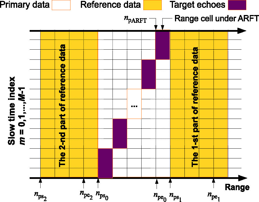
Radon-Fourier transform (RFT) is able to effectively overcome the coupling between the range cell migration (RCM) effect and Doppler modulation by searching along range and velocity dimensions jointly for the moving target, which depends on envelope alignment and Doppler phase compensation. However, without effective clutter suppression, clutter would also be intergraded via RFT. Thus, the adaptive RFT (ARFT) has been proposed to clutter suppression by introducing an optimal filter weight, which is determined from the clutter's covariance matrix as well as the steering vector for the moving target with the consideration of RCM effect. Nevertheless, the ARFT needs to address the difficulty for real implementation, i.e., computational complexity is too high to a large number of pulse samples. It is known that to obtain the inversion the sample covariance matrix (Rcn-1) is order M3, i.e., O(M3), in which $M$ is the order of the matrix. It is the most complexity consumed step in ARFT. In this paper, we propose a modified adaptive RFT (MARFT) method to obtain Rcn-1 with recursive computation, which takes the complexity order M2, i.e., O(M2). Simulations show that the proposed method has the same clutter suppression results as the conventional ARFT method, where the computational complexity is much lower.
Modified Adaptive RFT with Sample Covariance Matrix Inversion Recursive Estimation
2024-07-28
PIER C
Vol. 145, 173-179, 2024
download: 103
A Novel Miniaturized Dual-Passband Half-Mode Substrate Integrated Waveguide Filter Loaded with Back-to-Back CSRR
Min Li , Kejun Chang and Dongya Song
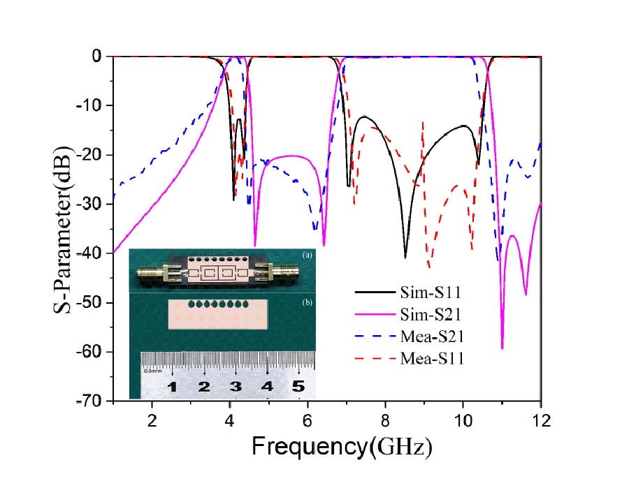
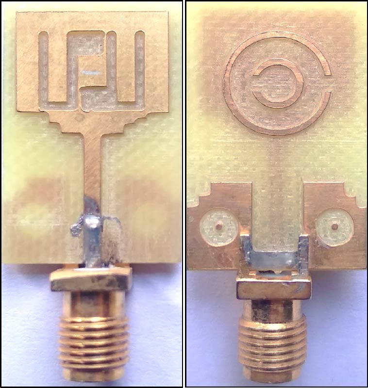
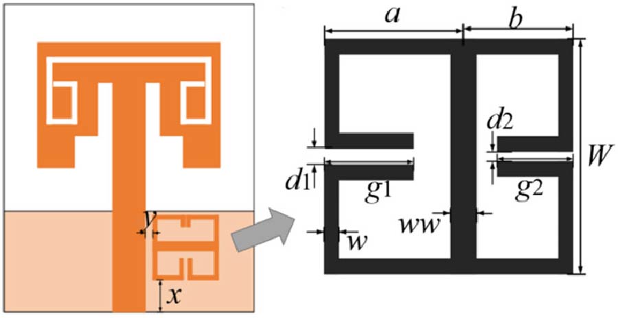
In order to solve the requirements of multi-channel communication applications, this paper proposes a miniaturized dual-passband substrate integrated waveguide filter with asymmetric passband response. The design uses a half-mode substrate integrated waveguide (HMSIW) cavity, which is loaded with a back-to-back complementary open resonant ring (CSRR) according to the vanishing mode propagation theory to generate a passband response lower than the HMSIW basic mode TE101, further reducing the cavity size. In addition, the band-resistive characteristics of the single-ring structure of the CSRR resonator are analyzed, and a C-slot is added at the feeder to improve the out-of-band characteristics of the second passband. Through simulation optimization and testing, the center frequency of the dual-passband filter is 4.05 GHz/8.64 GHz; the relative bandwidth is 16%/44%, the insertion loss of both passbands is better than 0.8 dB; the physical test results are consistent with the simulation ones; and the size of the filter is only 0.42λg × 0.14λg. It shows that the proposed filter has the characteristics of small size and low loss, and can be widely used in multi-channel RF front-end systems in the field of wireless communication.
A Novel Miniaturized Dual-passband Half-mode Substrate Integrated Waveguide Filter Loaded with Back-to-back CSRR
2024-07-27
PIER C
Vol. 145, 167-172, 2024
download: 103
Design of Broadband Microstrip Grid Array Antenna Based on Dielectric Filling
Yuxuan Fang and Xinhua Wang
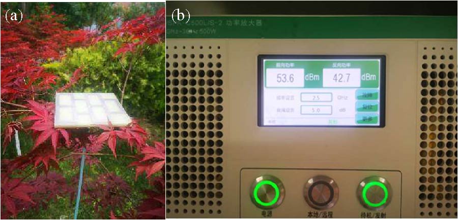
Based on dielectric filling, a microstrip grid antenna with six grids is designed in this paper. The broadband characteristics are achieved by increasing the thickness of substrate. An N-type penetrating coaxial port is adopted to feed the antenna for realizing high power capacity. Firstly, the influence of the grid parameters variation on the reflection coefficient was analyzed through the simulation model. Then the structure of the antenna was optimized. Secondly, a prototype of the antenna was fabricated according to the optimized results. The measured results of the fabricated antenna show that the impedance bandwidth of the designed microstrip grid antenna can reach (taking |S11| < -10 dB as the reference) 24.3% ranging from 2.22 GHz to 2.83 GHz. The power capacity of the antenna in the 2.5 GHz can reach 229 Watts according to the measured result of power capacity. Therefore, the designed antenna can be effectively applied in the field of high power irradiation test and high power interference performance test of electronic equipment.
Design of Broadband Microstrip Grid Array Antenna Based on Dielectric Filling
2024-07-25
PIER C
Vol. 145, 153-165, 2024
download: 111
A Proximity-Fed Multi-Band Printed Antenna for Wireless Communication Applications
Ali Jabbar Salim , Jabbar K. Mohammed , Hussam Al-Saedi and Jawad K. Ali
This paper introduces a new triple-band antenna driven indirectly by a feed line for multiple wireless applications. The structure of this antenna is based on the creation of a set of slots and slits on the ground plane mounted on a substrate with relative permittivity of 4.4 and thickness of 1.6 mm. On the other hand, a 50-ohm microstrip feed line has been fixed. It is found that the proposed antenna offers a triple-band fashion with -10 dB impedance bandwidths suitable for most recent wireless applications. The first band extends from 1.6 GHz to 2.8 GHz, which covers LTE bands (1, 2, 3, 4, 9, 10, 23, 24, 25, 33, 34, 35, 36, 37, 39 and 40), 2.4 GHz-Bluetooth, and 2.45 GHz ISM. The second band extends from 3.38 GHz to 3.6 GHz, which covers most WiMAX applications, while the third band reconciles 5.8 GHz-ITS and 2.4/5.8 GHz-WLAN. A prototype of the proposed antenna has been successfully simulated, fabricated, and measured.
A Proximity-fed Multi-band Printed Antenna for Wireless Communication Applications
2024-07-24
PIER C
Vol. 145, 141-152, 2024
download: 133
A 12-Unit Asymmetric Mirror-Coupled Loop Antenna for 5G Smartphones
Wanying Ren , Zhonggen Wang , Wenyan Nie , Weidong Mu , Chenlu Li , Mingqing Wang and Wenshi You
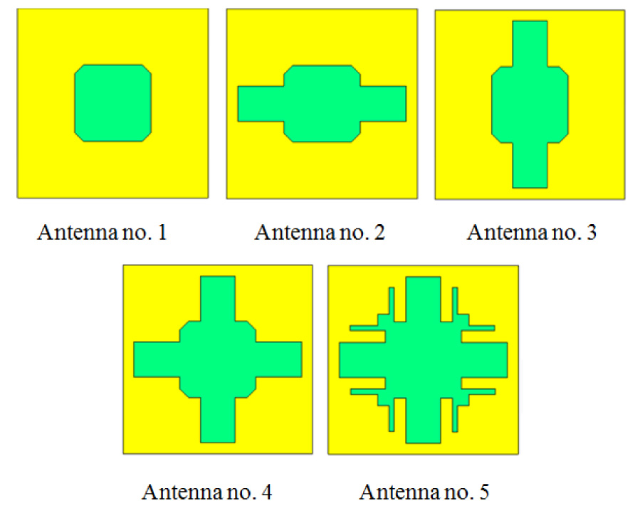
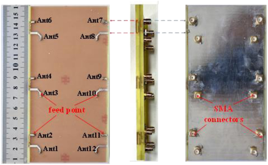
This paper introduces a 12-element asymmetric mirror-coupled loop antenna for integration into 5G smartphones. The proposed antenna includes six identical asymmetrically mirrored (AM)-coupled building blocks, each consisting of two gap-coupled loop antennas, with each building block dimensioning a mere 12×7 mm2. The unique architecture of the proposed antenna yields an isolation performance exceeding 14 dB without the necessity for ancillary decoupling elements and effectively covers the dual-band 5G mobile frequency bands of 3.3-3.6 GHz and 4.8-5.0 GHz. The antenna was optimized using simulation software HFSS, and the results indicate an antenna's envelope correlation coefficient of less than 0.016 and an efficiency range of 72%-81%. Finally, the performance of single-hand and double-hand handset smartphone modes is discussed, which still exhibit good radiation and MIMO performance under both modes, demonstrating their stability in practical applications. Simulation and measurement results indicate that the proposed 12-element MIMO antenna holds great promise for 5G smartphone applications.
A 12-unit Asymmetric Mirror-coupled Loop Antenna for 5G Smartphones
2024-07-24
PIER C
Vol. 145, 129-140, 2024
download: 87
Optimal Service Area Partitioning for Wireless Communication Systems and a Multibeam Antenna with Contoured Beams for the Equipotential Coverage of This Area
Alexander V. Shishlov , Yury V. Krivosheev , Vladimir V. Denisenko and Boris A. Levitan
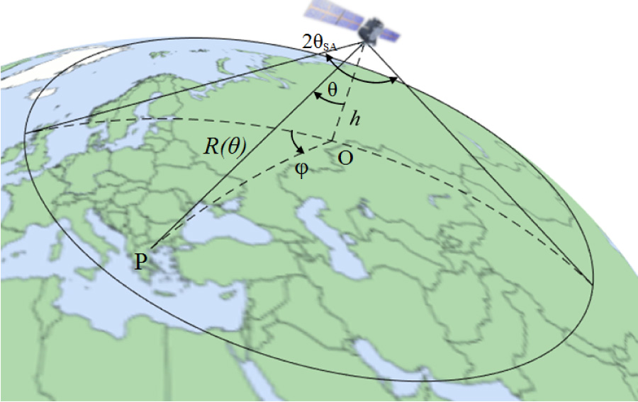
In a number of wireless communication systems with multibeam antennas, the distance from the antenna to subscribers in different parts of the service area varies significantly. Such systems include high-altitude platform station communication systems, communication systems based on low Earth orbit and medium Earth orbit satellites, and several others. If such a system uses an antenna with identical beams, the throughputs of communication lines in different cells can differ by more than an order of magnitude due to the variation in distance. To equalize throughputs across all cells within the service area, an antenna with different beams can be employed. The gain of these beams should be proportional to the squared slant ranges to the centers of the served cells. The gain of a beam can be modified by altering its size and shape. This paper proposes a method for service area partitioning in communication systems that accounts for the slant range to subscribers. It determines the shapes and profiles of the ideal contoured beams and presents optimized contoured beams for a real antenna.
Optimal Service Area Partitioning for Wireless Communication Systems and a Multibeam Antenna with Contoured Beams for the Equipotential Coverage of This Area
2024-07-22
PIER C
Vol. 145, 119-127, 2024
download: 142
A Diamond-Type Broadband Microstrip Patch Antenna with a Folded Floor
Han Lin and Yiwei Tao
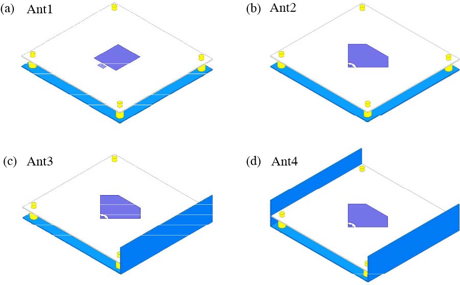
In this paper, a diamond-shaped broadband high-gain microstrip patch antenna based on a folded floor structure is proposed. The overall dimensions of the antenna are 108 mm × 100 mm × 25 mm. Additionally, it contains a radiating microstrip patch, a folded ground plane, and a capacitive feed strip. The broadening of the antenna's operating band is achieved by enhancing the microstrip radiating patch and the capacitive feed band. The original rectangular structure was transformed into a rhombic structure, enabling the radiating patch to absorb the current more effectively and achieve a better impedance match for the antenna operating around 5 GHz. The radiation performance of the antenna is maximized by utilizing the folded floor structure. Measured results show that the impedance bandwidth of the antenna is about 61.5% (2.84 GHz-5.36 GHz), covering 5G dual bands. Meanwhile, the peak gain reaches 12.6 dBi, and the average gain reaches 10.7 dBi.
A Diamond-type Broadband Microstrip Patch Antenna with a Folded Floor
2024-07-21
PIER C
Vol. 145, 107-117, 2024
download: 135
Gap-Coupled Designs of Hexagonal Microstrip Antennas on Thinner Substrate Using Cavity-Backed Structure
Amit A. Deshmukh , Kushal Katira , Aarti G. Ambekar , Venkata A. P. Chavali , Hari Vasudevan and Tushar V. Sawant
Multi-resonator gap-coupled design of coaxially fed half-hexagonal microstrip antennas is proposed in 900 MHz frequency range. It yields an impedance bandwidth of 32 MHz (3.28 %) on a thinner FR4 substrate (~0.01λg). Reduction in patch area in the gap-coupled design is achieved by employing the ground plane slots. Slots reduce the fundamental mode resonance frequency on each patch, thereby realizing wideband response in a lower frequency region. With impedance bandwidth of 26 MHz (3.4%), slot cut ground plane design provides patch area reduction by 38.13% and frequency reduction by 21.8%. Enhancement in the broadside gain on a thinner lossy substrate in the gap-coupled designs is achieved by integrating a cavity-back structure, which provides gain increment by nearly 2.5-3 dBi. Thus, the proposed work outlines a technique that enhances the bandwidth and reduces the patch size with an increment in the gain, on a thinner lossy substrate. An experimental verification for the obtained results is carried out that shows a close agreement.
Gap-coupled Designs of Hexagonal Microstrip Antennas on Thinner Substrate Using Cavity-backed Structure
2024-07-20
PIER C
Vol. 145, 101-105, 2024
download: 132
A Dual-Notched Ultra-Wideband Monopole Antenna Based on Frequency Selective Surface Technology
Yingjie Du and Mingxin Liu
To solve the problem of antenna miniaturization and mutual interference between the communication band of the UWB system and other wireless communication system bands, this paper proposes a UWB monopole antenna which has frequency notch characteristics. By applying two pairs of Split Ring Resonator (SRR) structures on a CPW transmission line, a coupling resonance is generated in a specific frequency band, and the antenna has a dual frequency notch and a wide band notch function. The measured results show that the antenna has good band-notch characteristics in the frequency ranges of 3.3 GHz to 4 GHz and 5.1 GHz to 6.2 GHz, suppressing ultra-wideband interference between WiMAX (3.3 GHz~3.8 GHz) and WLAN (5.15 GHz~5.35 GHz and 5.725 GHz~5.825 GHz) in a wireless communication system. The volume of the antenna is 40 mm × 36 mm × 1 mm, and the measured results are compared with the simulated model results. Besides, the measured and simulated results have a good consistency.
A Dual-notched Ultra-wideband Monopole Antenna Based on Frequency Selective Surface Technology
2024-07-19
PIER C
Vol. 145, 91-100, 2024
download: 168
Reconfigurable Compact Wide-Band Quad-Port Antennas Based on a Varactor Diode for Sub-6 GHz 5G Communications
Qasim Hadi Kareem
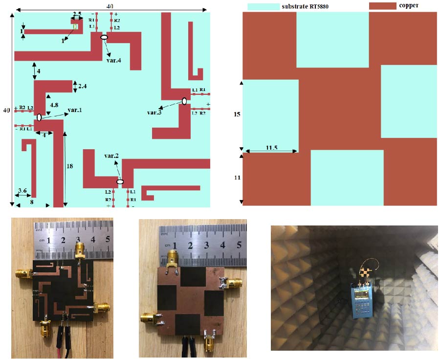
The rapid expansion of wireless communication systems has spurred a growing demand for adaptable multiple-input multiple-output (MIMO) antennas capable of accommodating diverse frequency bands and operational environments. This paper presents a compact quad-port wide-band tuning-reconfigurable MIMO antenna tailored specifically for 5G applications operating within the sub-6 GHz spectrum. The proposed design enhances isolation levels (>18 dB) and augments pattern diversity by utilizing four orthogonal radiating elements. Integrating a C-shaped monopole element with a matching stub facilitates frequency tuning via a varactor diode, ensuring a consistent radiation pattern. The lower and upper resonant bands could be fine-tuned by adjusting the varactor diode's reverse-biased voltage within the allowed range of 0.5 to 10 V. These bands are 4 to 5.18 GHz and 5.45 to 6.65 GHz, respectively. The proposed antenna system's four C-shaped elements are placed on a 40 × 40 mm2 ground plane and mounted on a Rogers RT5880 substrate that is 0.8 mm thick with a relative permittivity of 2.2. This design is well suited for various wireless applications and cognitive radio networks due to its compatibility with sub-6 GHz frequency bands and wide-band tuning capabilities.
Reconfigurable Compact Wide-band Quad-port Antennas Based on a Varactor Diode for Sub-6 GHz 5G Communications
2024-07-18
PIER C
Vol. 145, 83-90, 2024
download: 115
Sampling Strategy Selection for EMC Simulation Surrogate Model in Uncertainty Analysis and Electromagnetic Optimization Design
Shenghang Huo , Jinjun Bai , Shaoran Gao and Yule Liu
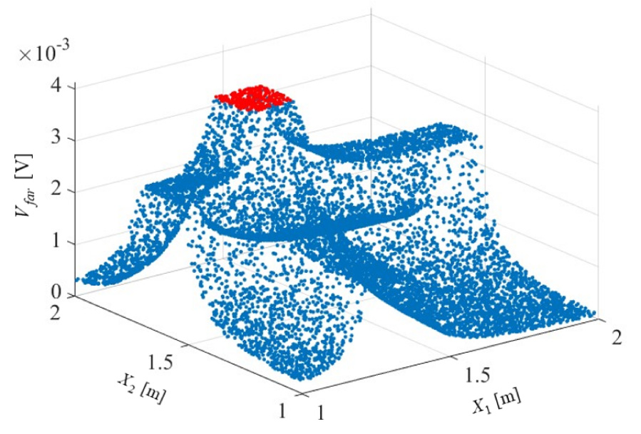
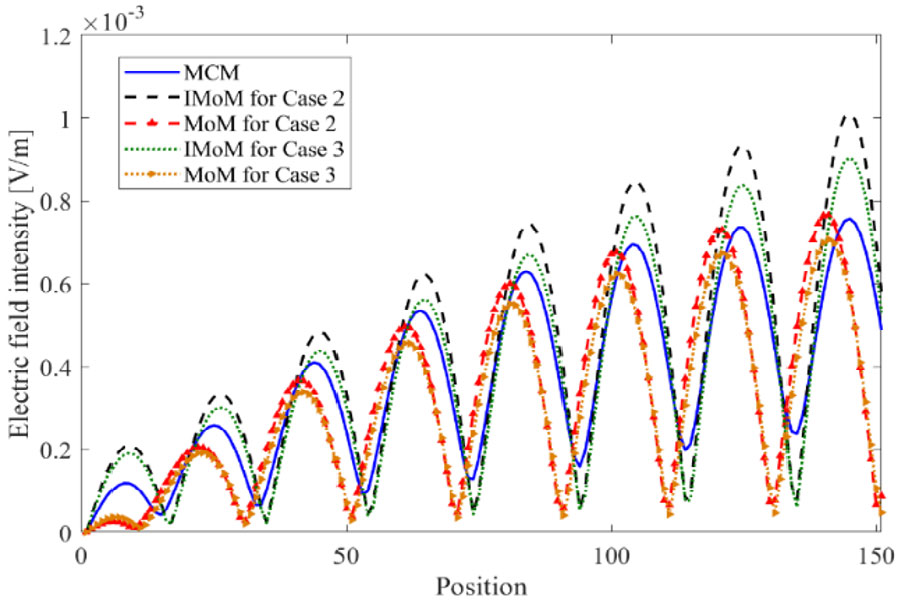
Surrogate models have been gradually promoted in electromagnetic compatibility (EMC) simulation in recent years, and two typical application scenarios are uncertainty analysis and electromagnetic optimization design. The surrogate model can simulate the forward EMC simulation process as accurately as possible with relatively few sampling points. The choice and number of sampling points will directly determine the accuracy of the surrogate model. The purpose investigated by uncertainty analysis and electromagnetic optimization design is different. How to choose appropriate sampling strategies is worth discussing, but there are fewer studies in the field at this stage. This paper applies a cascaded cable crosstalk example to explore the accuracy of the surrogate model under different sampling strategies, which provides a theoretical level of guidance for the application of the surrogate model in EMC simulation. The study enables the surrogate model to be better suited for two application scenarios: uncertainty analysis and electromagnetic optimization design.
Sampling Strategy Selection for EMC Simulation Surrogate Model in Uncertainty Analysis and Electromagnetic Optimization Design
2024-07-18
PIER C
Vol. 145, 75-82, 2024
download: 111
Miniaturized Novel Multi Resonance Monopole Planar Antenna with Slots, Slits, Split Ring Resonator
Prasanna L. Zade and Sachin S. Khade
The proposed multi-resonant monopole antenna has a compact design and operates between 2.9 and 6 GHz, effectively covering the full 5G sub-6 GHz spectrum (N77/N78/N79) as well as WLAN frequency ranges. This Miniaturized Multi-resonance Monopole Planar Antenna (MMMPA), having dimensions 25 × 16 × 1.6 mm3 (L x W x h), is ideally suited for wireless communication devices and systems. The antenna achieves triple resonances, encompassing the frequency bands from 2.9 to 6 GHz, through an inventive construction consisting of rectangular patch, U slots, key-shaped slots, split ring resonators, and annular rings forming an electromagnetic band-gap (EBG) structure. A strong degree of agreement and correlation amongst the simulation and measurement findings attests to the antenna's dependable operation. Even though the patch size was reduced by around 65%.
Miniaturized Novel Multi Resonance Monopole Planar Antenna with Slots, Slits, Split Ring Resonator
2024-07-16
PIER C
Vol. 145, 63-74, 2024
download: 139
Dual-Band Circularly Polarized Antenna with Wide Axial-Ratio and Gain Beamwidths for High-Precision BDS Applications
Junhao Ren , Hongmei Liu , Youjie Zeng , Zhongbao Wang and Shao-Jun Fang
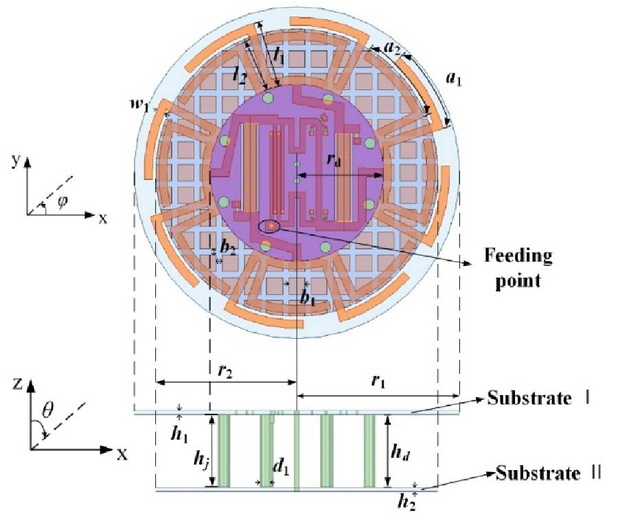
In the paper, a dual-band circularly polarized (CP) antenna with wide axial-ratio and gain beamwidths is proposed for high-precision BDS applications. The radiator is consisted of four groups of dipoles, eight metal columns, and a reflector. The half-power beam width (HPBW) can be effectively increased by bending a portion of the dipole into an arc and loading a series of metal columns on the ground. Besides, a reactive impedance structure (RIS) is inserted serves as a reflector to improve the axial ratio beamwidth (ARBW) and obtain unidirectional radiation. At the same layer of the dipoles, a four-feed network is presented to provide stable quadrature-phase excitation. For validation, the designed antenna is manufactured, where the overall size is 0.48λ0 × 0.48λ0 × 0.12λ0. Measurement results suggest that the proposed antenna is capable of operating efficiently within the frequency range of 1.17-1.22 GHz (4.2%) and 1.5-1.65 GHz (9.5%), which covers BDS B1 and B2 band. Moreover, at four main planes, the measured 3-dB ARBW/HPBW are more than 121°/121° and 150°/198° at 1.207 GHz and 1.561 GHz, separately. Consider that the proposed CP antenna exhibits wide overlapped beamwidth and small size, it is conducive to high-precision positioning in BDS applications.
Dual-band Circularly Polarized Antenna with Wide Axial-ratio and Gain Beamwidths for High-precision BDS Applications
2024-07-16
PIER C
Vol. 145, 53-61, 2024
download: 132
Design of 5G Multi-Frequency Antenna Based on Multi-Objective Sequential Domain Patching
Wenjian Zhu , Jiayi Chen , Panshi Hu , Zhi Song and Yanbing Xue
This paper introduces a 5G multi-frequency antenna design method based on multi-objective sequential domain patching. By etching helical metamaterials on radiation patches and loading asymmetric electric-inductive-capacitive metamaterials on the transmission line side, the antenna structure is designed and optimized using electromagnetic simulation software, HFSS, and MATLAB. The resulting multi-frequency antenna operates across multiple frequency bands: n1, n41, 3.5G, and 4.9G. To ensure antenna performance and radiation efficiency, the antenna multi-frequency bands are precisely controlled. The experimental results show that the error between each operating frequency band and target frequency bands of the antenna is within 7.2%. Compared with conventional antenna design methods, the use of metamaterials and intelligent algorithms to optimize the structural parameters and loading positions of metamaterials can improve antenna performance while shortening the design cycle. Overall, this research offers novel insights into the design of 5G high-performance antennas.
Design of 5G Multi-frequency Antenna Based on Multi-objective Sequential Domain Patching
2024-07-14
PIER C
Vol. 145, 45-51, 2024
download: 146
High-Performance Ceramic Filter Design Based on Six-Blind-Hole Coupling Structure
Yang Gao , Yun Xiu Wang , Xiao Tao Yao , Guangyong Wei and Jie Liu
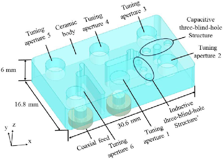
An innovative ceramic filter is presented in this paper. The filter is composed of six tuning apertures, coupling channels, and a six-blind-hole coupling structure. The six blind holes are divided into two groups: one situated between the first and second cavities to induce inductive coupling, and the other positioned between the second and third cavities to facilitate capacitive coupling. Employing this structure facilitates the formation of a cascade quadruple (CQ) coupling unit among the 1, 2, 3, and 4 resonant cavities, thereby introducing two transmission zeros. Subsequently, an analysis of the influences of the depth and spacing of each blind hole on the coupling coefficients is presented. Finally, to further validate the theory, the filter tailored for base station applications was designed and implemented. The measurement results demonstrate a center frequency of 3.5 GHz with a bandwidth of 200 MHz. In the passband, the insertion loss was below 1.2 dB, and the return loss surpassed 19 dB. The test outcomes align closely with the simulation, confirming the reliability of the design.
High-Performance Ceramic Filter Design Based on  Six-Blind-Hole Coupling Structure
2024-07-11
PIER C
Vol. 145, 35-43, 2024
download: 145
A Hybrid Excitation Variable-Leakage-Flux Machine with Magnetic-Bridge for Electric Vehicle
Ruipan Lu , Xinlong Huang , Zhangqi Liu and Xiping Liu
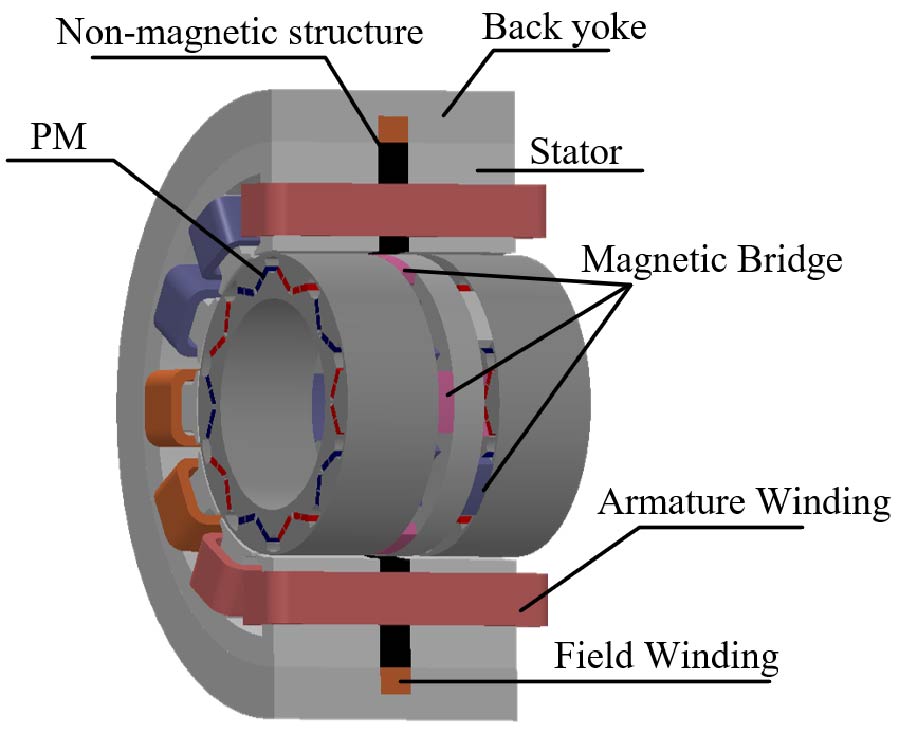
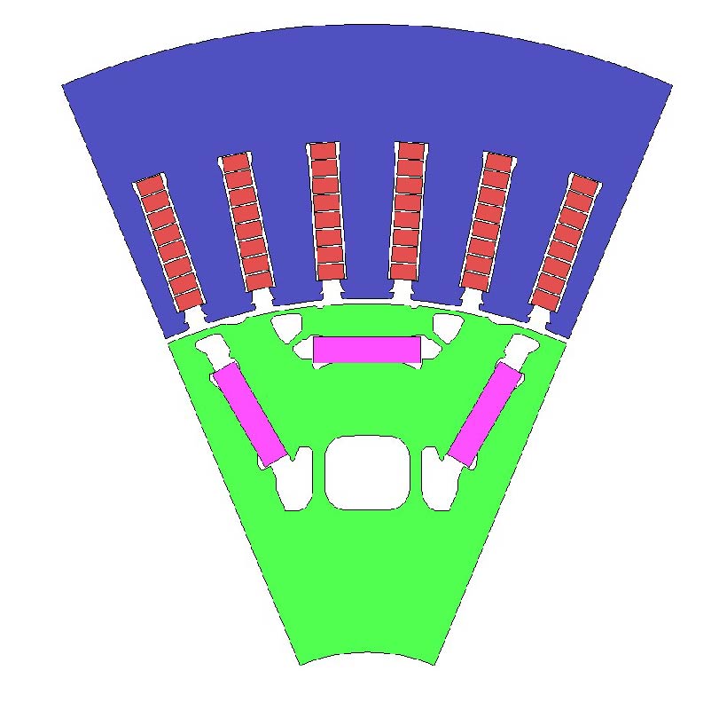
A hybrid excitation variable-leakage-flux machine (HE-VLFM) for electric vehicles is presented in this paper, which places the field windings on the outer side of the stator and provides an axial magnetic field through the magnetic ring and the magnetic bridge. The HE-VLFM proposed in this paper has a rotor permanent magnet to provide the main magnetic field and an excitation winding to provide a variable auxiliary magnetic field, which can fulfill the requirements of the electric vehicle drive system with large torque at low-speed and wide speed regulation range. The electromagnetic performance of the proposed HE-VLFM is evaluated using the equivalent magnetic circuit method and three-dimensional finite element analysis and the results show that the HE-VLFM has a well-developed regulating flux capability.
A Hybrid Excitation Variable-leakage-flux Machine with Magnetic-bridge for Electric Vehicle
2024-07-05
PIER C
Vol. 145, 27-34, 2024
download: 202
Study on ac Loss Suppression in Rectangular Winding Motors for Electric Vehicles
Shengyang Xu and Quanfeng Li
Currently, excessive AC loss in the rectangular winding motor used for electric vehicles poses a significant challenge, necessitating effective measures to suppress the losses. This paper focuses on the Prius IV motor, employing a finite element two-dimensional model established using JMAG software. The influence of conductor material and the number of rectangular winding layers on motor AC loss under various operating conditions is thoroughly analyzed. Maintaining a constant number of rectangular winding layers, aluminum (Al) conductors replace copper (Cu) conductors in 2-layer, 4-layer, 6-layer, and 8-layer configurations, respectively. AC losses are compared among motors with 4-layer, 6-layer, 8-layer, and 10-layer Cu rectangular windings, all having identical slot dimensions. Subsequently, the 10-layer Al conductor scheme is chosen to optimize motor design. The results demonstrate an average reduction in AC loss up to 59.24% after motor optimization, further reducing motor manufacturing costs.
Study on AC Loss Suppression in Rectangular Winding Motors for Electric Vehicles
2024-07-04
PIER C
Vol. 145, 21-26, 2024
download: 99
Key Practical Issues of the MoM Using in EMC Uncertainty Simulation
Jinjun Bai , Shaoran Gao , Shenghang Huo and Bing Hu
The Method of Moments (MoM) is widely used in Electromagnetic Compatibility (EMC) uncertain simulation due to its advantages, such as non-embedded simulation, high computational efficiency, and immunity from dimensional disasters. The theoretical research of the MoM has been relatively complete, but many of its key practical issues have not been fully discussed, which will result in the calculation accuracy in practical engineering applications falling short of theoretical expectations. With the help of the Feature Selective Validation (FSV) method, this paper analyzes and discusses two aspects. One is how to reasonably select the perturbation, and the other is the relationship between the uncertainty input size and the accuracy. By solving key practical issues of the MoM, the aim is to further promote it in the EMC field.
Key Practical Issues of the MoM Using in EMC Uncertainty Simulation
2024-07-02
PIER C
Vol. 145, 9-20, 2024
download: 109
A Spatial Electromagnetic Field Analysis Method for Estimating the Dynamic Positions of Multiple Mobile High-Frequency Power Supplies
Rui Zhang , Yanfeng Gao and Jixuan Wang
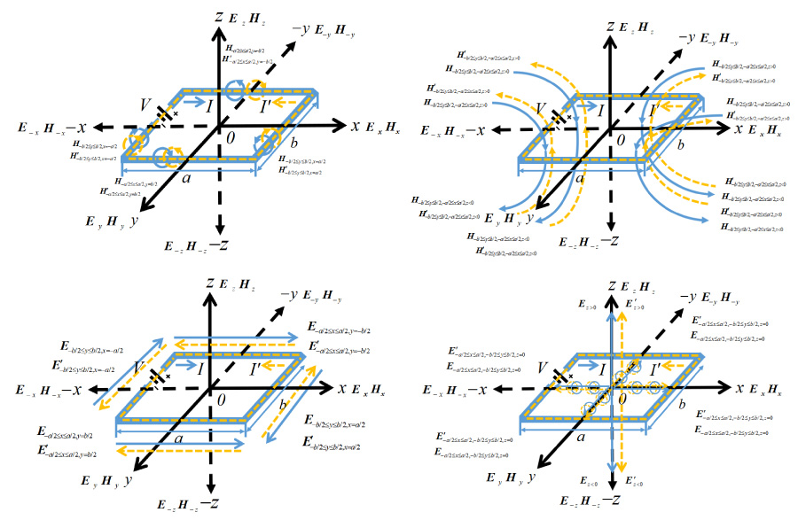
A spatial electromagnetic field analysis method is proposed by adding variable speed nodes to the circuit topology to estimate the optimal location of multiple mobile high-frequency power supplies at multiple nodes in this paper. In the process of continuous motion, the speed and position of motion affect the accumulated power and loss at the circuit node. At the same time, the transmission efficiency and delay characteristics of the high-frequency mobile power supply will also change with the precise positioning of the mobile power supply and the change of the spatially coupled electromagnetic field. The spatial electromagnetic field analysis method with variable speed nodes is used to divide the circuit topology of mobile high frequency power supply system according to the number of nodes. The continuous motion of variable speed nodes is used to simulate the real-time positioning of multiple mobile high-frequency power sources. By analyzing the real-time variation of the high-frequency electromagnetic field at variable speed nodes, the quantitative relationship between the electromagnetic characteristics of the node space and the speed and positioning of the mobile power supply is established. Finally, the fast optimal positioning of each mobile high-frequency power supply in the continuous moving process is obtained. Compared with the position estimation results obtained by the traditional relation calculation method, when the size is greater than 100, the proposed method can locate the position of multi-mobile high-frequency power supply faster and more accurately, and the circuit efficiency reaches 90%. The simulation results verify the correctness of the theoretical analysis.
A Spatial Electromagnetic Field Analysis Method for Estimating the Dynamic Positions of Multiple Mobile High-frequency Power Supplies
2024-07-01
PIER C
Vol. 145, 1-8, 2024
download: 122
Theoretical Analysis of Bandwidth Requirements for Damped Sinusoid Measurement
Jing Yang , Wei Wu , Zhizhen Zhu , Zhitong Cui , Yayun Dong , Xin Nie , Fei Cao and Chuan He
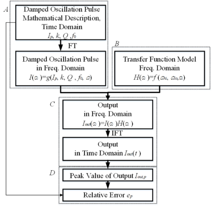
High altitude electromagnetic pulse (HEMP) couples to cables and introduces interference into the connected electronic equipment. Responses arising from the transient electromagnetic field typically follow an exponentially damped sinusoid behavior. Thus, damped sinusoids with different parameters are recommended in the International Electrotechnical Commission (IEC) standards as typical injected waveform for HEMP conducted immunity test. To guarantee the compliance of the injected pulse, accurate measurement of the injected pulse is needed. Wideband proportional current sensors are often applied to measure the injected damped sinusoid. However, bandwidth requirements of wideband proportional current sensor for damped sinusoid measurement are not specified. In this paper, two formulae are deduced to establish the relationships between the bandwidth requirements and the fundamental resonance frequency of the damped sinusoid to be measured. It is convenient and simple for the on-site engineers to check whether the bandwidth of the proportional current sensor is suitable by the formulae. Monte-Carlo simulation is conducted in support of the recommended formulae.
Theoretical Analysis of Bandwidth Requirements for Damped Sinusoid Measurement