Vol. 119
Latest Volume
All Volumes
PIERC 150 [2024] PIERC 149 [2024] PIERC 148 [2024] PIERC 147 [2024] PIERC 146 [2024] PIERC 145 [2024] PIERC 144 [2024] PIERC 143 [2024] PIERC 142 [2024] PIERC 141 [2024] PIERC 140 [2024] PIERC 139 [2024] PIERC 138 [2023] PIERC 137 [2023] PIERC 136 [2023] PIERC 135 [2023] PIERC 134 [2023] PIERC 133 [2023] PIERC 132 [2023] PIERC 131 [2023] PIERC 130 [2023] PIERC 129 [2023] PIERC 128 [2023] PIERC 127 [2022] PIERC 126 [2022] PIERC 125 [2022] PIERC 124 [2022] PIERC 123 [2022] PIERC 122 [2022] PIERC 121 [2022] PIERC 120 [2022] PIERC 119 [2022] PIERC 118 [2022] PIERC 117 [2021] PIERC 116 [2021] PIERC 115 [2021] PIERC 114 [2021] PIERC 113 [2021] PIERC 112 [2021] PIERC 111 [2021] PIERC 110 [2021] PIERC 109 [2021] PIERC 108 [2021] PIERC 107 [2021] PIERC 106 [2020] PIERC 105 [2020] PIERC 104 [2020] PIERC 103 [2020] PIERC 102 [2020] PIERC 101 [2020] PIERC 100 [2020] PIERC 99 [2020] PIERC 98 [2020] PIERC 97 [2019] PIERC 96 [2019] PIERC 95 [2019] PIERC 94 [2019] PIERC 93 [2019] PIERC 92 [2019] PIERC 91 [2019] PIERC 90 [2019] PIERC 89 [2019] PIERC 88 [2018] PIERC 87 [2018] PIERC 86 [2018] PIERC 85 [2018] PIERC 84 [2018] PIERC 83 [2018] PIERC 82 [2018] PIERC 81 [2018] PIERC 80 [2018] PIERC 79 [2017] PIERC 78 [2017] PIERC 77 [2017] PIERC 76 [2017] PIERC 75 [2017] PIERC 74 [2017] PIERC 73 [2017] PIERC 72 [2017] PIERC 71 [2017] PIERC 70 [2016] PIERC 69 [2016] PIERC 68 [2016] PIERC 67 [2016] PIERC 66 [2016] PIERC 65 [2016] PIERC 64 [2016] PIERC 63 [2016] PIERC 62 [2016] PIERC 61 [2016] PIERC 60 [2015] PIERC 59 [2015] PIERC 58 [2015] PIERC 57 [2015] PIERC 56 [2015] PIERC 55 [2014] PIERC 54 [2014] PIERC 53 [2014] PIERC 52 [2014] PIERC 51 [2014] PIERC 50 [2014] PIERC 49 [2014] PIERC 48 [2014] PIERC 47 [2014] PIERC 46 [2014] PIERC 45 [2013] PIERC 44 [2013] PIERC 43 [2013] PIERC 42 [2013] PIERC 41 [2013] PIERC 40 [2013] PIERC 39 [2013] PIERC 38 [2013] PIERC 37 [2013] PIERC 36 [2013] PIERC 35 [2013] PIERC 34 [2013] PIERC 33 [2012] PIERC 32 [2012] PIERC 31 [2012] PIERC 30 [2012] PIERC 29 [2012] PIERC 28 [2012] PIERC 27 [2012] PIERC 26 [2012] PIERC 25 [2012] PIERC 24 [2011] PIERC 23 [2011] PIERC 22 [2011] PIERC 21 [2011] PIERC 20 [2011] PIERC 19 [2011] PIERC 18 [2011] PIERC 17 [2010] PIERC 16 [2010] PIERC 15 [2010] PIERC 14 [2010] PIERC 13 [2010] PIERC 12 [2010] PIERC 11 [2009] PIERC 10 [2009] PIERC 9 [2009] PIERC 8 [2009] PIERC 7 [2009] PIERC 6 [2009] PIERC 5 [2008] PIERC 4 [2008] PIERC 3 [2008] PIERC 2 [2008] PIERC 1 [2008]
2022-04-23
PIER C
Vol. 119, 275-285, 2022
download: 335
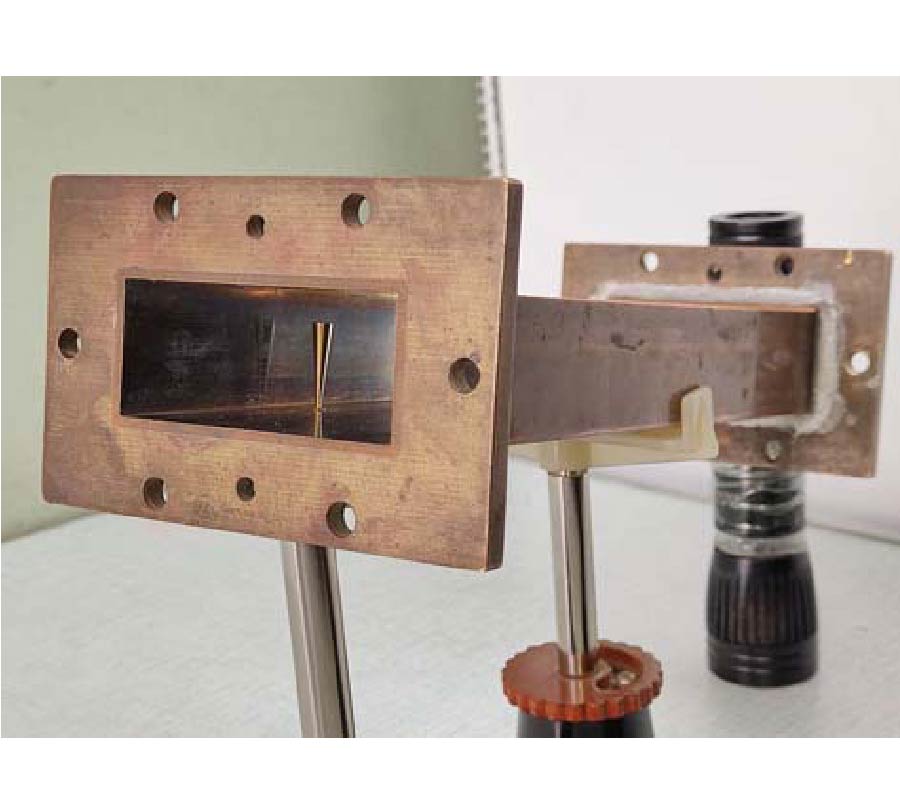
Scattering of Electromagnetic Waves by Impedance Biconical Vibrators in А Free Space and in a Rectangular Waveguide
Mikhail Nesterenko , Andrey V. Gomozov , Viktor A. Katrich , Sergey L. Berdnik and Victor I. Kijko
A problem of scattering of electromagnetic waves by thin impedance biconical vibrators in а free space and in a rectangular waveguide is solved by an asymptotic averaging method and a generalized method of induced electromotive forces (EMF). An influence of the change of vibrator radius upon energy and spatial characteristics is numerically studied. Theoretical results are compared with the experimental data.
SCATTERING OF ELECTROMAGNETIC WAVES BY IMPEDANCE BICONICAL VIBRATORS IN А FREE SPACE AND IN A RECTANGULAR WAVEGUIDE
2022-04-22
PIER C
Vol. 119, 255-273, 2022
download: 429
UWB Compact Microstrip Patch Antenna with High Directivity Using Novel Star-Shaped Frequency Selective Surface
Rajesh Kumar and Devi Charan Dhubkarya
This paper presents a single element ultra-wideband (UWB) microstrip patch antenna with high directivity. In this work, techniques like partial ground and modification of the patch have been used to achieve the UWB. The designed antenna consists of a modified U-shaped radiating patch with a microstrip feed attached directly to it. The initial U-shaped radiating patch is modified by attaching an inverted trapezium on both sides of the feed line. Two parasitic patches are introduced near the feed structure of the antenna after etching away two rectangular slots with appropriate dimensions. Moreover, the proposed structure consists of a partial ground plane which contributes to the UWB nature. Modifications in the form of square and triangular slot etching are carried out in this part of the proposed structure. The proposed antenna is compact with dimensions of 16 mm × 19 mm × 1.6 mm. Finally, gain enhancement of the proposed structure is done by placing a Frequency Selective Surface (FSS) behind the proposed antenna with an air spacer in between the structures. A novel FSS unit cell is proposed, and its performances are checked experimentally. Later, FSS is combined with the antenna, and measured peak gain of 9.7 dBi is obtained experimentally. The overall size of the structure is 62.5 mm × 52 mm × 24.9 mm.
UWB COMPACT MICROSTRIP PATCH ANTENNA WITH HIGH DIRECTIVITY USING NOVEL STAR-SHAPED FREQUENCY SELECTIVE SURFACE
2022-04-19
PIER C
Vol. 119, 245-254, 2022
download: 307
High-Gain Reflectarray with Compact Aperture Size and a Low Profile Using an Active-Integrated Feeding Antenna
Yen-Sheng Chen and Yu-Hong Wu
In this paper, we present a gain-enhancement technique for reflectarray applications with compact aperture size and a low profile. To increase antenna gain, reflectarrays are constructed as an electrically large aperture, and the feed is required to be of high directivity, which is accompanied by a longer focal length. This increases the dimensions in two aspects, including the physical aperture size and the profile of the overall structure. To obtain high gain with compact dimensions, we develop a reflectarray that uses an active-integrated feeding antenna. This feeding antenna is connected to a microwave power amplifier, which enhances the gain without reducing the half-power beam widths (HPBWs) of the patterns. Accordingly, the feed can be arranged with a shorter focal length, whereas the spillover efficiency is still high. Moreover, the power amplifier contributes additional gain of 20.6 dB, and thus the proposed structure can achieve realized gain as high as 44.5 dB with dimensions of 9.2 × 6.7 square wavelengths. Such a high-gain and compact antenna is particularly suitable for satellite applications.
HIGH-GAIN REFLECTARRAY WITH COMPACT APERTURE SIZE AND A LOW PROFILE USING AN ACTIVE-INTEGRATED FEEDING ANTENNA
2022-04-13
PIER C
Vol. 119, 235-244, 2022
download: 349
Bat Shaped Circularly Polarized Antenna for X and Ku Band Applications
Sweta Singh , Karunesh Srivastava , Farha Usman and Ram Suchit Yadav
A bat-shaped microstrip patch antenna is proposed with tri-band characteristics (11.0-11.5 GHz), (11.8-12.3 GHz), (13.0-14.3 GHz) and impedance bandwidth 4.4%, 4.1%, and 9.5% at resonant frequencies 11.37 GHz, 12.2 GHz, and 13.5 GHz, respectively. The proposed antenna exhibits peak gain of 2.6 dBi. The proposed microstrip patch antenna shows the dual band circularly polarized characteristics with two bands (11.0-13.0 GHz) and (13.2-14.0 GHz) and 3 dB axial-ratio (AR) impedance bandwidths 15% and 5.2%, respectively. Investigation of proposed antenna is done using evolution technique. The results are verified experimentally in terms of reflection coefficient, gain, axial ratio, and radiation pattern.
BAT SHAPED CIRCULARLY POLARIZED ANTENNA FOR X AND KU BAND APPLICATIONS
2022-04-10
PIER C
Vol. 119, 219-233, 2022
download: 361
A Flower Shaped Miniaturized 4×4 MIMO Antenna for UWB Applications Using Characteristic Mode Analysis
Ankireddy Chandra Suresh and Thatiparthi Reddy
A novel design of a 4×4 miniaturized UWB-MIMO (multiple-input, multiple-output) antenna with isolation improvement is proposed in this paper. The designing procedure of a flower-shaped MIMO antenna is done using characteristic mode analysis (CMA). The flower shaped UWB-MIMO antenna is made up of four symmetrical flower-shaped radiating elements that are isolated using an orthogonal method. The flower antenna's dimensions are 40x40x1.6 mm3 (0.44λ0x0.44λ0x0.017λ0). A flower-shaped radiator is used to get good the isolation in MIMO elements. Further isolation is enhanced by inserting a swastik-shaped stub on the ground to get return losses of S11<-10 and isolation of S12<-18 dB. The designed antenna covers the entire UWB (3.1-14 GHz) spectrum for impedance matching, including (10.7 to 11.7 GHz), 11 GHz (10.7 to 11.7 GHz), and 13 GHz (10.7 to 11.7 GHz) (12.75 to 13.25 GHz). Good diversity performance is achieved in the UWB and ITU range. The designed antenna has a gain of 5.5 dB, an efficiency of 89%, an impedance bandwidth of 123.61%, an envelope correlation coefficient of 0.0012, a diversity gain of nearer to 10 dB, a capacity channel loss of 0.29 bps/Hz, and a mean effective gain of less than -3.1 dB. The designed antenna is fabricated and tested. These simulated results are validated in state-of-the-art laboratories. According to the simulation and measurement results, this antenna is well suited for reliable wireless communication systems. The potentiality of the designed antenna is high, and the antenna is compact and portable.
A FLOWER SHAPED MINIATURIZED 4×4 MIMO ANTENNA FOR UWB APPLICATIONS USING CHARACTERISTIC MODE ANALYSIS
2022-04-07
PIER C
Vol. 119, 201-217, 2022
download: 374
Beamforming for 5G Cellular Communications with Analyzing the Linear and Circular Polarized Antenna Arrays Gain Effect
Amany Mohamed Saleh , Mahmoud Mohamed Elmesalawy , Korany Mahmoud and Ibrahim Ismail Ibrahim
Since massive multiple-input multiple-output (MIMO) array and beamforming significantly improve spectrum efficiency, where beamforming adapts the radiation pattern of the massive array, most previous studies focus on the MIMO beamforming optimization problem to maximize the utility of the system by assuming that a massive array consists of an isotropic antenna. This research work was conducted to investigate the beamforming optimization problem with practical elements in a MIMO array. By inserting the effect of a practical antenna array gain in the channel model, the impact of array elements feeding on the beamforming optimization problem could be illustrated. Furthermore, the beamforming optimization, non-convex issue, is reformulated to synonymous convex optimization issue, through a weighted minimum mean square error (WMMSE) technique. Consequently, a conformal array (CfA) with a half wavelength dipole element is proposed at the base station (BS). The simulation results display that the suggested WMMSE-beamforming technique performance with considering antenna array gain effect can yield much better and accurate system performance than the other algorithms. Eventually, to analyze the impact of array gain on the optimization problem solution in addition to boot the network capacity, a curl antenna array in octagonal prism geometry is created. The curl antenna is circularly polarized and has a high gain compared to the half-wavelength dipole.
BEAMFORMING FOR 5G CELLULAR COMMUNICATIONS WITH ANALYZING THE LINEAR AND CIRCULAR POLARIZED ANTENNA ARRAYS GAIN EFFECT
2022-04-05
PIER C
Vol. 119, 191-200, 2022
download: 458
A Dual-Band High-Gain Substrate Integrated Waveguide Slot Antenna for 5G Application
Umesh Singh and Rajesh Mishra
In this paper, the authors propose a small substrate integrated waveguide (SIW) slot antenna for future fifth generation (5G) communication systems. It works at 28 and 38 GHz. The proposed geometry consists of horizontal and vertical vias as well as a central circular ring. The cut slots in the etched center circular ring create a significant capacitive loading effect, lowering the lower resonating mode. Further, the introduced circular ring slot resonates on TE101 and TE102 modes at 28 and 38 GHz, respectively. The measured impedance bandwidths are 27.77-28.02 GHz and 37.99-38.10 GHz. Peak gains in the lower and upper bands are measured to be 6.96-7.15 dBi and 8.10-8.22 dBi, respectively. At 28 and 38 GHz, the observed half-power beam-widths (HPBWs) are 74.5˚ and 79.2˚, respectively. Considering these performance results, such as single-layer dual-bands, high gain, small size, and good radiation efficiency, the designed SIW slot antenna is suitable for future millimeter-wave 5G applications.
A DUAL-BAND HIGH-GAIN SUBSTRATE INTEGRATED WAVEGUIDE SLOT ANTENNA FOR 5G APPLICATION
2022-03-31
PIER C
Vol. 119, 177-190, 2022
download: 471
Tri-Band Bandpass Filter Using Mixed Short/Open Circuited Stubs and q -Factor with Controllable Bandwidth for WAS, ISM, and 5G Applications
Omar Christian Massamba , Pierre Moukala Mpele , Franck Moukanda Mbango and Desire Lilonga-Boyenga
Designing a multi-band bandpass filter (BPF) with controllable bandwidths is an alternative process to several technologies suggested by researchers. Hence, this paper presents a tri-band BPF in microstrip technology where T-shaped short-and-open stubs have alternating positions to use the maximally flat theory, based on the overall ABCD parameters of the circuit. The combination of the design Q-factor and the operating frequency to mismatch the design is the technique basis. The proposed structure comprises the quarter wavelength (λ/4) line section to develop a tri-band BPF frequency. All stubs are symmetrical relative to the center axis, while the prototype has been fabricated on a wafer of 22.42x7.62 mm2. Using an FR4 HTG-175 with a thickness of 1-mm, dielectric constant εr=4.4, and loss tangent tanδ=0.02, the (4.06-4.283) GHz, (5.877-6.408) GHz, and (14.281-14.589) GHz are obtained referring to a 10-dB of the return loss. In contrast, the insertion losses at the center frequencies are 2.107/1.354/4.08 dB and the fractional bandwidths of 2.134%, 5.346%, and 8.645%, respectively. These covers WAS (including RLAN), ISM, and 5G applications. However, the attenuation coefficient is between 1.326 dB and 4.368 dB. The tri-band BPF prototype was validated using the Anritsu MS4642B 20 GHz Vector Network Analyzer. The measured and E-simulated results have been compared with good agreement.
TRI-BAND BANDPASS FILTER USING MIXED SHORT/OPEN CIRCUITED STUBS AND Q-FACTOR WITH CONTROLLABLE BANDWIDTH FOR WAS, ISM, AND 5G APPLICATIONS
2022-03-30
PIER C
Vol. 119, 161-175, 2022
download: 387
Design and Characteristics Mode Analysis of a Cantor Set Fractal Monopole Antenna for IoT Applications
Geeta B. Kalkhambkar , Rajashri Khanai and Pradeep Chindhi
A four-level iterated cantor set fractal antenna for Internet of Things (IoT) applications is proposed in this work. The proposed antenna operates at 2.4 GHz and for the range of 5 GHz to 8.5 GHz. In the 5 GHz to 8.5 GHz range it covers a Wi-Fi802.11 Standard (4.9 GHz, 5 GHz, 5.9 GHz, 6 GHz), 6.56 GHz, and at the lower band it covers WiMax (2.5-2.7 GHz). The proposed antenna offers a gain up to 4 dBi with an efficiency up to 90%. The designed antenna is experimented with a partial ground plane, with and without notch to perceive its effects on S11 parameters. The antenna and its feed location is optimized for improved performance. The proposed antenna is analysed using the theory of characteristics mode analysis. The antenna is fabricated on a low-cost FR4 substrate with a dielectric constant of 4.4 anda substrate height of 1.6 mm. The antenna performance in terms of S11, VSWR, and Gain is validated by measuring the performance in an anechoic chamber with Agilent N5247A Vector Network Analyser (VNA). The antenna is designed and optimized in mentor graphics software and CST Studio. The results show good agreement between the simulated and measured performances of the antenna. The optimized geometry of the antenna is compact having overall dimensions of 32 mm×22 mm×1.6 mm and suitable for short-range IoT applications.
DESIGN AND CHARACTERISTICS MODE ANALYSIS OF A CANTOR SET FRACTAL MONOPOLE ANTENNA FOR IOT APPLICATIONS
2022-03-29
PIER C
Vol. 119, 145-159, 2022
download: 422
A Compact Microstrip Four Port Dual Circularly Polarized MIMO Antenna for Sub-6G Application
Zhong Yu , Leiyan Huang , Qi Gao and Yanping Chen
This article proposes a compact microstrip four-port dual circularly polarized (CP) multiple-input multiple-output (MIMO) antenna with polarization diversity for Sub-6G band. The proposed MIMO antenna consists of four antenna elements, two of which are left-hand circular polarization (LHCP), and the other two are right-hand circular polarization (RHCP). The circular polarization of each antenna element of the MIMO antenna is achieved by a microstrip feed line and a slotted ground plane with two rectangular strips. A novel decoupling element of the antenna composed of I-shaped and II-shaped metal strips is cross-connected and merged between the ground planes of the antenna to obtain wide axial ratio bandwidth and high isolation. The size of the proposed antenna is 55×55×1.6 mm3. The antenna of the impedance bandwidth (S11 ≤ -10 dB) is 3.28-3.80 GHz (14.6%), and the axial ratio bandwidth (AR ≤ 3 dB) is 2.85-3.87 GHz (30.3%). Inter-element isolation less than -16 dB and the envelope correlation coefficient (ECC) less than 0.07 are achieved between the ports of the antenna. The proposed MIMO antenna achieves full coverage of CP characteristics within the impedance bandwidth. The proposed antenna is beneficial to the application of Sub-6G band. At the same time, it is also suitable for dual circular polarization communication and polarization diversity system.
A COMPACT MICROSTRIP FOUR PORT DUAL CIRCULARLY POLARIZED MIMO ANTENNA FOR SUB-6G APPLICATION
2022-03-29
PIER C
Vol. 119, 135-144, 2022
download: 567
Modified Patch and Ground Plane Geometry with Reduced Resonant Frequency
Khan Masood Parvez , Tabish Ali and Satyabrata Maiti
A higher degree of miniaturization technique is presented based on frequency reduction method for a rectangular patch antenna by introducing slot on the radiating patch with unchanged antenna configuration. To realize the frequency reduction technique, a rectangular patch is design to operate at the fundamental frequency. Then a slot on the radiating patch is introduced and as an effect of slot, fundamental resonant frequency is shifted in left side in reflection coefficient plot. The percentage of reduction resonant frequency is 65.80% where 2.31 GHz is the fundamental frequency, and 790 MHz is the operating frequency of slot integrated patch geometry. In addition, we introduced another similar slot on the ground plane, and as a result, resonant frequency shifted from 790 MHz to 729 MHz caused by 68.44% reduction in resonant frequency with unchanged antenna dimension. Equivalent circuits have been analyzed for each antenna topology. To verify the simulated results, prototypes are fabricated and complied with measured results.
MODIFIED PATCH AND GROUND PLANE GEOMETRY WITH REDUCED RESONANT FREQUENCY
2022-03-24
PIER C
Vol. 119, 125-134, 2022
download: 272
Dual Band Two Element Rim Based MIMO Antennas with Coupling Manipulation for Low SAR Mobile Handsets
Muhammad Ali Jamshed , Tim W. C. Brown and Fabien Héliot
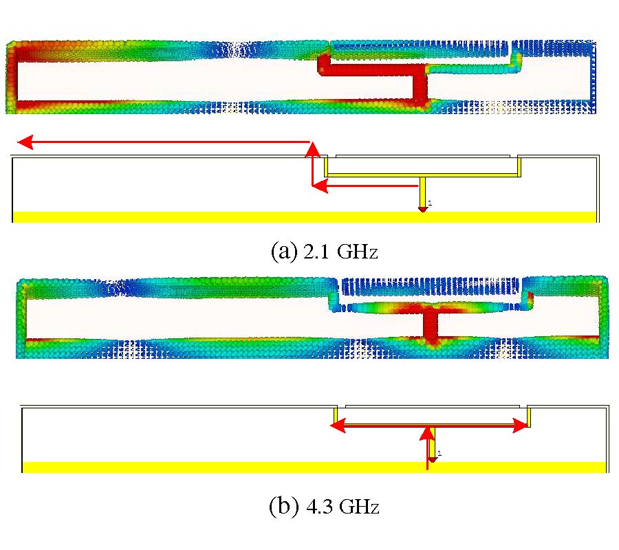
In this paper, the mutual coupling from a multiple-input-multiple-output (MIMO) rim antenna has been utilized to control the level of specific absorption rate (SAR), when the mobile handset comes in close contact to the human body. The proposed antenna is capable of operating at 2.1 GHz and 4.3 GHz, respectively. A periodic defective ground structure (DGS) in conjunction with diodes and capacitors are used to manipulate the coupling between antenna elements. The working of the proposed dual band antenna design is validated using the characteristic mode analysis (CMA), and the current distribution. The MIMO performance is studied by using envelope correlation coefficient (ECC) and loss in capacity analysis. The effect of hand and LCD on the antenna performance is shown. The SAR analysis shows up to 30% reduction, in comparison to the baseline value of the SAR of the proposed antenna design.
DUAL BAND TWO ELEMENT RIM BASED MIMO ANTENNAS WITH COUPLING MANIPULATION FOR LOW SAR MOBILE HANDSETS
2022-03-22
PIER C
Vol. 119, 115-124, 2022
download: 402
Arrow Cross Shape Slotted Fractal Antenna with Enhanced Bandwidth for Wi-Fi/WiMAX /WLAN Applications
Rani Rudrama Kodali , Polepalli Siddaiah and Mahendra Nanjappa Giriprasad
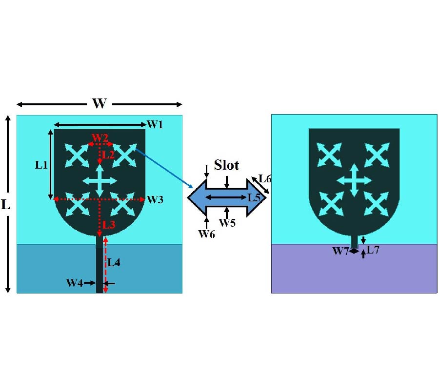
A fractal antenna with enhanced bandwidth (BW) from 2.62 GHz to 5.2 GHz is presented for Wi-Fi applications. The antenna is designed to achieve a wider BW, and it consists of a rectangular shape patch attached to a half circular disc. The antenna is fed by microstrip feed model. The ground plane of the antenna is maintained partial with a slot at centre. Double head arrow cross shaped slots are etched on the radiating element to form the proposed fractal antenna. While the centre slot is made to look like + symbol, the surrounding four fractal slots are made to look like × symbol. FR4 substrate with dielectric constant 4.4 with thickness 1.6 mm is used to design the antenna. The overall size of the antenna is maintained compact with dimensions 44 mm × 40 mm. The dimensions of the fractal slots are varied, and the operating band is tuned. The proposed antenna covers from 2.62 GHz to 5.2 GHz with BW 2.58 GHz. The step-by-step implementation of the fractal antenna and comparative analysis are presented with the help of reflection coefficient curves. While the proposed antenna covers wideband, it showed peak resonance at dual operating frequencies at 3.2 GHz and 4.8 GHz. The designed antenna-maintained gain of 2.96 dBi and 3.47 dBi at 3.2 GHz and 4.8 GHz frequencies, respectively. The proposed antenna performance is presented with the help of reflection coefficient, VSWR, gain, field distributions, and radiation pattern curves. The simulated and measured analysis comparison showed good agreement making the designed antenna a good candidate for wideband Wi-Fi applications.
ARROW CROSS SHAPE SLOTTED FRACTAL ANTENNA WITH ENHANCED BANDWIDTH FOR WI-FI/WIMAX/WLAN APPLICATIONS
2022-03-22
PIER C
Vol. 119, 97-114, 2022
download: 280
Multi-Objective Optimization and Analysis of Six-Pole Outer Rotor Hybrid Magnetic Bearing
Gai Liu , Zhihao Ma , Huangqiu Zhu , Jingbo Sun and Junqi Huan
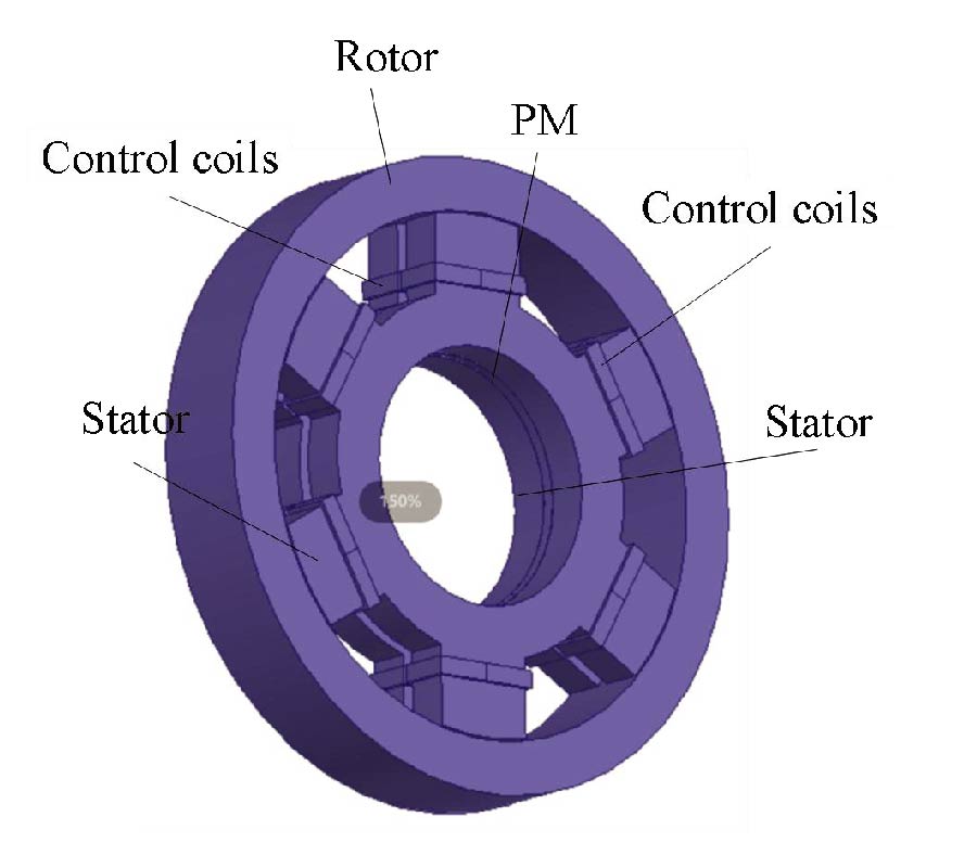
The multi-objective optimization of the six-pole outer rotor hybrid magnetic bearing (OSHMB) not only solves the nonlinear and strong coupling problems of the three-pole magnetic bearing (THMB), but also makes the magnetic bearing structure more compact and improves the maximum bearing capacity. Firstly, the structure and working principle of the OSHMB are introduced, and the mathematical models of suspension forces are established by the Maxwell tensor method. Secondly, the key parameters of the OSHMB are multi-objective optimized, and an optimal set of parameters is obtained through the sensitivity analysis, constructing the response surface model, and the multi-objective optimization based on the genetic algorithm. Based on the optimal parameters, the force current characteristics and maximum carrying capacity of the OSHMB are analyzed. Finally, the experimental platform is built. The suspension experiments, anti-interference experiments and load loading experiments are performed. It can be seen that the maximum bearing capacity of the OSHMB is about 9.6% higher than that of the SHMB.
MULTI-OBJECTIVE OPTIMIZATION AND ANALYSIS OF SIX-POLE OUTER ROTOR HYBRID MAGNETIC BEARING
2022-03-22
PIER C
Vol. 119, 81-96, 2022
download: 317
Full Duplex High Speed Data Transmission Based on Partially Coupled Coils in Wireless Power Transmission Systems
Jianxiong Li and Wenlong Yang
For full duplex communication, a signal parallel transfer method based on partial power transmission couplers is proposed in this paper. The power transfer uses a serial LC compensation structure topology, and the data transmission channel adopts a double coupling resonant circuit. In terms of power transmission, some power coupling inductors and power compensation capacitors form a power resonance network with a high frequency trap function, which can isolate the influence of signal transmission. Therefore, there is no need for an additional trap, which reduces power loss and the space occupied by the structure. In terms of signal transmission, the partial coupling coil method can increase the coupling frequency and the data transfer rate. In addition, the signal transmission circuit has the characteristics of dual resonance frequencies. The forward and reverse signals modulate the carrier at different resonance frequencies to realize full duplex communication. Finally, the simulation results prove that the scheme is practicable for full duplex communication and parallel transmission of power, achieving anoutput power of 1.4 KW, and the highest transmission rate can reach 1 Mbps.
FULL DUPLEX HIGH SPEED DATA TRANSMISSION BASED ON PARTIALLY COUPLED COILS IN WIRELESS POWER TRANSMISSION SYSTEMS
2022-03-14
PIER C
Vol. 119, 65-79, 2022
download: 415
Large Intelligent Surface-Assisted Wireless Communication and Path Loss Prediction Model Based on Electromagnetics and Machine Learning Algorithms
Wael Elshennawy
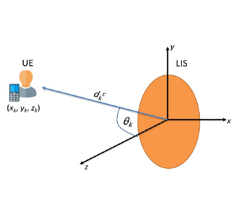
This paper presents the application of machine learning-based approach toward prediction of path loss for the large intelligent surface-assisted wireless communication in smart radio environment. Two bagging ensemble methods, namely K-nearest neighbor and random forest, are exploited to build the path loss prediction models by using the training dataset. To generate the data samples without having to run measurement campaign, a path loss model is developed owning to the similarity between the large intelligent surface-assisted wireless communication and the reflector antenna system. Simple path loss expression is deduced from the system gain of the reflector antenna system, and it is used to generate the data samples. Simulation results are presented to verify the prediction accuracy of the path loss predictions models. The prediction performances of the trained path loss models are assessed based on the complexity and accuracy metrics, including R2 score, mean absolute error, and root mean square error. It is demonstrated that the machine learning-based models can provide high prediction accuracy and acceptable complexity. The K-nearest neighbor algorithm outperforms random forest algorithm, and it has smaller prediction errors.
LARGE INTELLIGENT SURFACE-ASSISTED WIRELESS COMMUNICATION AND PATH LOSS PREDICTION MODEL BASED ON ELECTROMAGNETICS AND MACHINE LEARNING ALGORITHMS
2022-03-09
PIER C
Vol. 119, 49-63, 2022
download: 549
The Design and Implementation of an RF Energy Harvesting System Using Dynamic Pi-Matching, Enabling Low-Power Device Activation and Energy Storage
Beragama Vithanage Sandaru Suwan , Wijesekara Withana Gamage Vidula , Wanniarachchi Kankanamge Indika Lasantha Wanniarachchi , Chandima Helakumara Manathunga and Sasani Jayawardhana
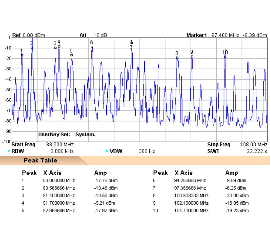
Radio-frequency electromagnetic waves can be harnessed to produce an alternative source of energy to replace batteries in many low-power device applications. An efficient radio frequency (RF) energy harvesting circuit was designed and constructed using a dynamic Pi-matching network in order to convert frequency-modulated electromagnetic waves in the range of 88-108 MHz to direct current through a 3-step process. The circuit consists of a 50 Ω copper plate dipole antenna, a Pi impedance matching network, and a five-stage voltage doubler circuit. These three modules are connected through SubMiniature version A (SMA) connectors for convenient assembly. The dynamic Pi matching technique for RF energy harvesting is theoretically explained and simulated in the Advance Design System software environment. The experimental values obtained in this proposed work are in good agreement with the simulations. The harvesting system is capable of producing up to 14.3 V direct current voltage across a 100 kΩ load in field tests carried out at a displacement of 760 m from a transmission tower. At 6.7 km from the tower, a DC value of 61.5 mV was still obtainable at the ground level. The direct-current power that was generated through the energy harvesting was applied for the demonstration of three tasks with satisfactory results: illuminating a light-emitting diode, energy storage in a Panasonic VL2020 rechargeable battery, and activation of a TMP20AIDCKT temperature sensor in an urban area which enabled low power device activation and energy storage.
THE DESIGN AND IMPLEMENTATION OF AN RF ENERGY HARVESTING SYSTEM USING DYNAMIC PI-MATCHING, ENABLING LOW-POWER DEVICE ACTIVATION AND ENERGY 
STORAGE
2022-03-09
PIER C
Vol. 119, 31-47, 2022
download: 364
A New Fault Location Method Independent of Line Parameters
Lihui Zhao , Jingwei Zhu , Hongzhe Yang and Bin Gu
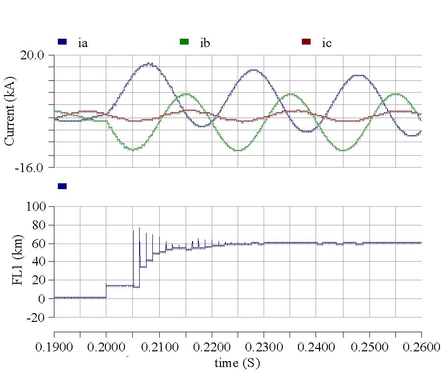
To restore power feeding as soon as possible and reduce repair costs and labor, a precise and robust fault location method for transmission lines is proposed. This method is based on the current and voltage synchronously collected by the phasor measurement units (PMUs) at two terminals of the line and does not require line parameters to calculate the fault distance. The line parameter is not approximately constant, but is affected by power load, temperature, and humidity, which affects the accuracy of most fault location algorithms that rely on line parameters. Therefore, the method proposed in this paper is robust and accurate. The method is based on the sequence fault component network and synchronous measurement technology, which is not affected by the system's pre-fault state, fault type, fault inception angle, and fault phase. Then, the method is verified in PSCAD/EMTDC by choosing different path resistances, fault types, fault inception angles, load currents, and line transpositions. A large number of simulation results show that the proposed method has high accuracy and robustness.
A NEW FAULT LOCATION METHOD INDEPENDENT OF LINE PARAMETERS
2022-03-08
PIER C
Vol. 119, 17-30, 2022
download: 310
Compact Negative-Permittivity Microstrip Patch Antenna for End-Fire Radiation
Masoud Ahmadi , Bruce Veidt and Loïc Markley
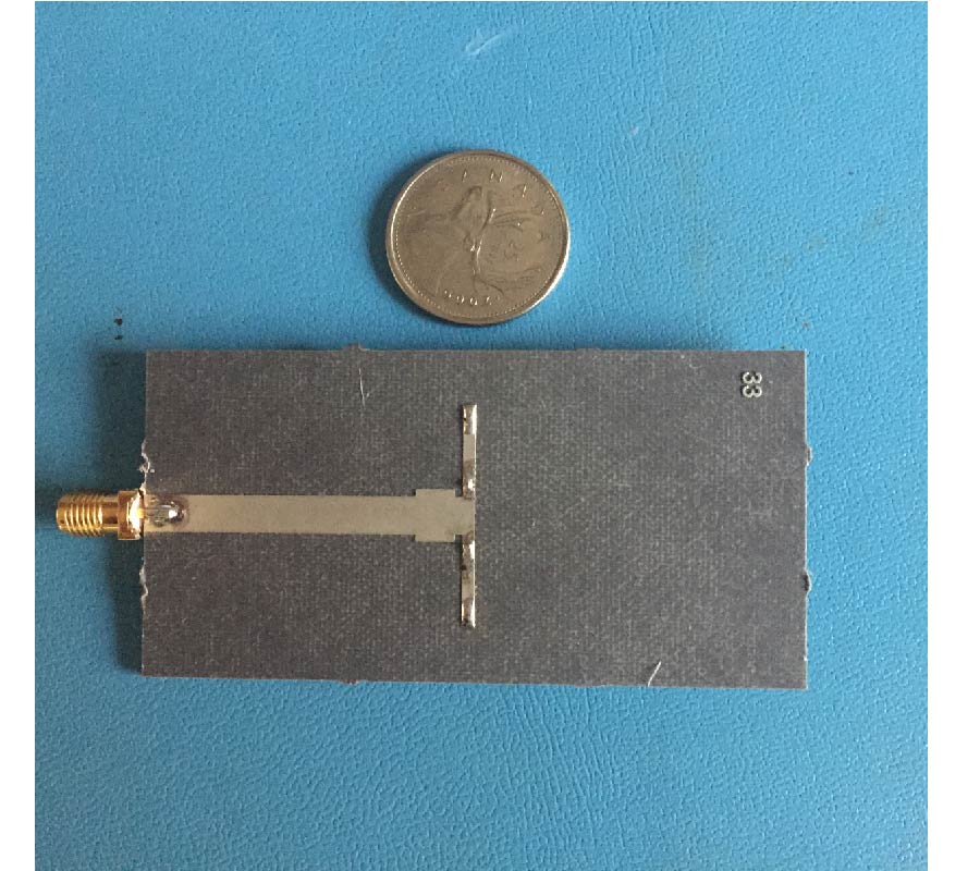
We propose a compact microstrip patch antenna that uses a negative permittivity substrate to achieve an end-fire radiation pattern. The antenna is designed to operate at X-band frequencies with a patch footprint of 0.9λ × 0.05λ and a thickness of λ/20. We show that loading a narrow patch with a negative permittivity substrate introduces an effective shunt inductance that resonates with the strong fringing capacitance of the patch. At resonance, the electric field is vertically polarized and approximately uniform across the patch, producing transverse nulls that improve the directivity of the antenna. The negative permittivity substrate is implemented using a thin-wire effective medium with four vias spread across the patch. The antenna is matched to 50 Ω using a quarter-wavelength transformer. The fabricated antenna operates at 10.8 GHz with a peak return loss of 30 dB and a bi-directional directivity of 10.7 dBi. The antenna has a 10-dB impedance bandwidth of 3.8% and radiates with a simulated efficiency of 93%.
COMPACT NEGATIVE-PERMITTIVITY MICROSTRIP PATCH ANTENNA FOR END-FIRE RADIATION
2022-02-28
PIER C
Vol. 119, 1-16, 2022
download: 301
Redefining of the Radar Cross Section and the Antenna Gain to Make Them Suitable for Surface Wave Propagation
Quentin Herbette , Muriel Darces , Nicolas Bourey , Stéphane Saillant , Florent Jangal and Marc Hélier
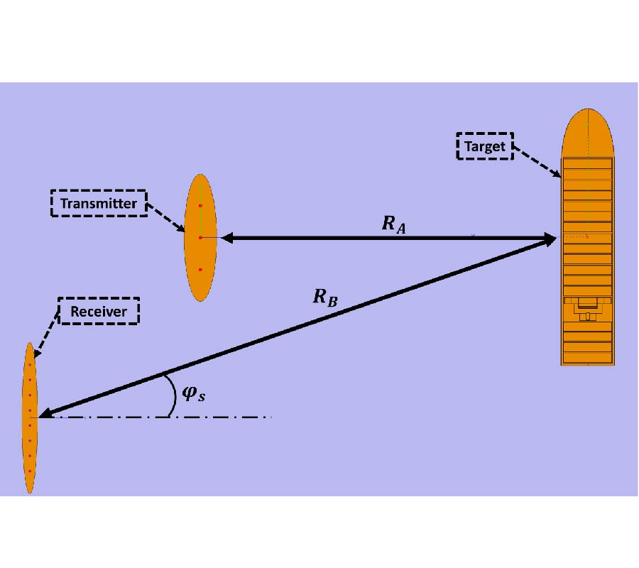
This paper deals with a new definition of the Radar Cross Section (RCS) suitable for surface wave propagation in the HF band. Indeed, it can be shown that the classical definition of the RCS is dependent on distance for this kind of propagation. Also, in simulation, with the classical definition, the power estimated on the receivers using the radar equation is inaccurate. This is an issue for the performance assessment of High Frequency Surface Wave Radars. Thanks to the analysis of different wave propagation models, the differences between the space wave propagation and surface wave propagation have been highlighted. The required modifications of the RCS can then be performed. The proposed new definition is explained and justified in the paper and has been successfully applied to the computation of the RCS of naval targets. In addition, the implementation of this normalization term into the radar equation, and conversely the gain, is discussed. It can be observed that the received power, determined with the definitions adjusted to the surface wave propagation, is accurate. The different obtained results are illustrated and commented.
REDEFINING OF THE RADAR CROSS SECTION AND THE ANTENNA GAIN TO MAKE THEM SUITABLE FOR SURFACE WAVE PROPAGATION