Vol. 90
Latest Volume
All Volumes
PIERC 149 [2024] PIERC 148 [2024] PIERC 147 [2024] PIERC 146 [2024] PIERC 145 [2024] PIERC 144 [2024] PIERC 143 [2024] PIERC 142 [2024] PIERC 141 [2024] PIERC 140 [2024] PIERC 139 [2024] PIERC 138 [2023] PIERC 137 [2023] PIERC 136 [2023] PIERC 135 [2023] PIERC 134 [2023] PIERC 133 [2023] PIERC 132 [2023] PIERC 131 [2023] PIERC 130 [2023] PIERC 129 [2023] PIERC 128 [2023] PIERC 127 [2022] PIERC 126 [2022] PIERC 125 [2022] PIERC 124 [2022] PIERC 123 [2022] PIERC 122 [2022] PIERC 121 [2022] PIERC 120 [2022] PIERC 119 [2022] PIERC 118 [2022] PIERC 117 [2021] PIERC 116 [2021] PIERC 115 [2021] PIERC 114 [2021] PIERC 113 [2021] PIERC 112 [2021] PIERC 111 [2021] PIERC 110 [2021] PIERC 109 [2021] PIERC 108 [2021] PIERC 107 [2021] PIERC 106 [2020] PIERC 105 [2020] PIERC 104 [2020] PIERC 103 [2020] PIERC 102 [2020] PIERC 101 [2020] PIERC 100 [2020] PIERC 99 [2020] PIERC 98 [2020] PIERC 97 [2019] PIERC 96 [2019] PIERC 95 [2019] PIERC 94 [2019] PIERC 93 [2019] PIERC 92 [2019] PIERC 91 [2019] PIERC 90 [2019] PIERC 89 [2019] PIERC 88 [2018] PIERC 87 [2018] PIERC 86 [2018] PIERC 85 [2018] PIERC 84 [2018] PIERC 83 [2018] PIERC 82 [2018] PIERC 81 [2018] PIERC 80 [2018] PIERC 79 [2017] PIERC 78 [2017] PIERC 77 [2017] PIERC 76 [2017] PIERC 75 [2017] PIERC 74 [2017] PIERC 73 [2017] PIERC 72 [2017] PIERC 71 [2017] PIERC 70 [2016] PIERC 69 [2016] PIERC 68 [2016] PIERC 67 [2016] PIERC 66 [2016] PIERC 65 [2016] PIERC 64 [2016] PIERC 63 [2016] PIERC 62 [2016] PIERC 61 [2016] PIERC 60 [2015] PIERC 59 [2015] PIERC 58 [2015] PIERC 57 [2015] PIERC 56 [2015] PIERC 55 [2014] PIERC 54 [2014] PIERC 53 [2014] PIERC 52 [2014] PIERC 51 [2014] PIERC 50 [2014] PIERC 49 [2014] PIERC 48 [2014] PIERC 47 [2014] PIERC 46 [2014] PIERC 45 [2013] PIERC 44 [2013] PIERC 43 [2013] PIERC 42 [2013] PIERC 41 [2013] PIERC 40 [2013] PIERC 39 [2013] PIERC 38 [2013] PIERC 37 [2013] PIERC 36 [2013] PIERC 35 [2013] PIERC 34 [2013] PIERC 33 [2012] PIERC 32 [2012] PIERC 31 [2012] PIERC 30 [2012] PIERC 29 [2012] PIERC 28 [2012] PIERC 27 [2012] PIERC 26 [2012] PIERC 25 [2012] PIERC 24 [2011] PIERC 23 [2011] PIERC 22 [2011] PIERC 21 [2011] PIERC 20 [2011] PIERC 19 [2011] PIERC 18 [2011] PIERC 17 [2010] PIERC 16 [2010] PIERC 15 [2010] PIERC 14 [2010] PIERC 13 [2010] PIERC 12 [2010] PIERC 11 [2009] PIERC 10 [2009] PIERC 9 [2009] PIERC 8 [2009] PIERC 7 [2009] PIERC 6 [2009] PIERC 5 [2008] PIERC 4 [2008] PIERC 3 [2008] PIERC 2 [2008] PIERC 1 [2008]
2019-03-06
PIER C
Vol. 90, 265-279, 2019
download: 326
DC Transformer Compensation for Efficiency Improvement of Electric Vehicles Wireless Charging Systems
Yao He , Mei Liu , Xintian Liu , Xinxin Zheng , Guojian Zeng and Jiangfeng Zhang
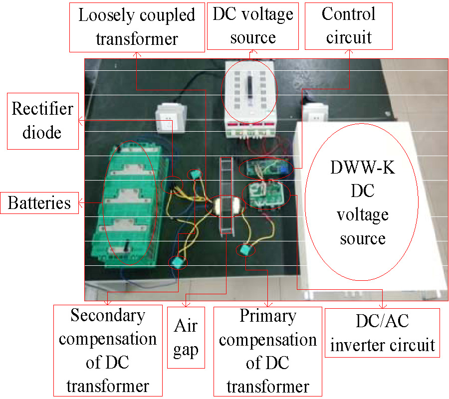
A wireless charging system for electric vehicles has two parts which are located inside and outside the vehicle respectively, and energy is transmitted from the outside part to inside part through a loosely coupled transformer. The energy transmission efficiency is directly related to the power conversion efficiency of the entire wireless charging system. This paper aims to improve the transmission efficiency of the DC transformer of the wireless charging system through studying compensation design method of DC transformer. A dual-tap rectifier is applied at the secondary side of the transformer, and a capacitor is connected in series on the primary side. Two capacitors are connected in series on the secondary side. By quantitative analysis on DC transformer efficiency, the relationship among efficiency, switching frequency and compensation parameter is obtained. The compensated DC transformer realizes soft switch and further improves transformer efficiency. Finally, simulation and experiment on the wireless charging system with magnetic induction are conducted to verify the improved transformer design. The simulated and experimental results show that the average compensated DC transformer efficiency has been improved by 1.248%. Thus the designed DC transformer can effectively improve the energy transmission efficiency, and reduce voltage stress of the power device.
DC TRANSFORMER COMPENSATION FOR EFFICIENCY IMPROVEMENT OF ELECTRIC VEHICLES WIRELESS CHARGING SYSTEMS
2019-03-05
PIER C
Vol. 90, 253-263, 2019
download: 311
Unsymmetrical Finger-Shape DGSs for Developing a Compact, High-Order, Harmonic-Suppressed Bandpass Filter
Yih-Dar Chen and Chien-Hao Liu
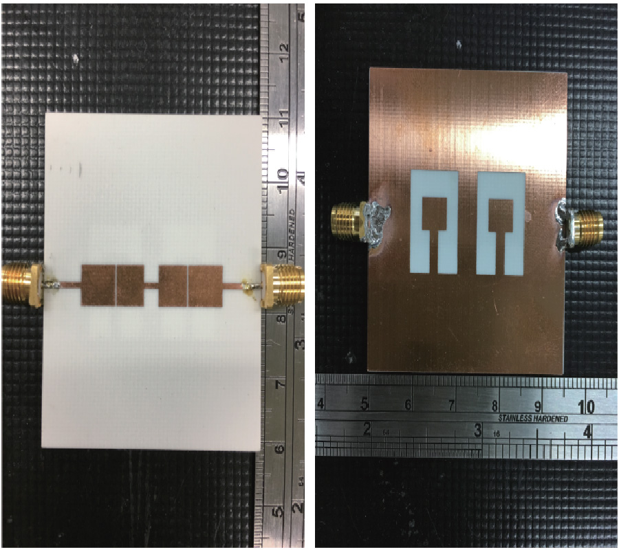
Defected ground structures (DGSs) are often utilized in planar filters and antennas for compactness and spurious frequency suppressions by creating defects or slots on the ground planes. One disadvantage of conventional DGS filters is that the overall dimension increases as the order of the filter increases. In this research, we proposed an asymmetric finger-shape DGS which created multiple equivalent LC resonators when combining with a capacitive microstrip gap on the top. In contrast to the conventional high-order DGS filter by generating many DGSs on the ground plane, the finger-shape DGS provided a high-order bandpass response with one single DGS due to the capacitances between the top metallic strip and the ground plane. Therefore, we developed a wide-band, high-order, and spurious frequency suppressed microstrip bandpass filter with a compact size. To achieve these features, different filter design techniques were exploited including stepped impedance resonator (SIR), series-coupled resonator, and nger-shape DGSs. The main advantage of our DGS filter was that it had a higher-order and wider bandpass responses than other harmonic-suppressed work. A prototype was designed, fabricated, and measured with a calibrated vector network analyzer (VNA) where the simulations matched with the measurements. The finger-shape DGS filter demonstrated a passband centered at 2.35 GHz with a fractional bandwidth of 72.3%, the spurious frequency suppression up to 8.5f0 where f0 was the center frequency of the passband, and a compact size of 0.034λ02 where λ0 was the wavelength corresponding to f0.
UNSYMMETRICAL FINGER-SHAPE DGSS FOR DEVELOPING A COMPACT, HIGH-ORDER, HARMONIC-SUPPRESSED BANDPASS FILTER
2019-03-05
PIER C
Vol. 90, 237-252, 2019
download: 357
Path Loss Measurement and Prediction in Outdoor Fruit Orchard for Wireless Sensor Network at 2.4 GHz Band
Tossaporn Srisooksai , Kamol Kaemarungsi , Junichi Takada and Kentaro Saito
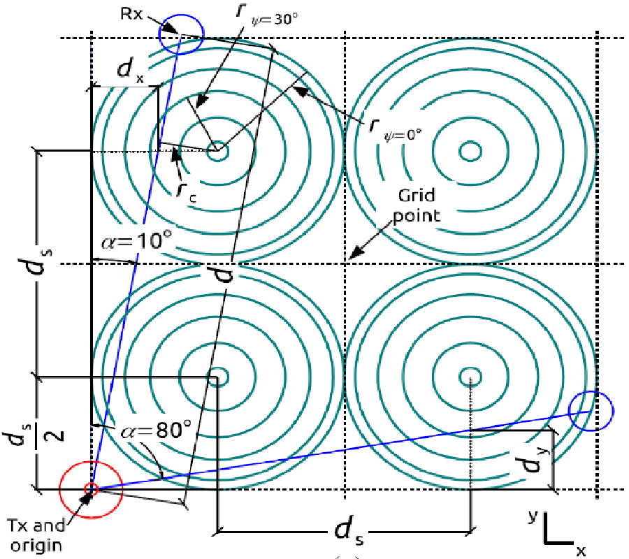
This work describes the path loss of radio propagation for wireless sensor network in the outdoor fruit orchard which is one of the common agriculture environments. The measurement was conducted in the jackfruit orchard in the 2.45 GHz band. Unlike other studies conducted in the fruit orchard environments, the variation of path loss over the relative angles between the plant rows and the line-of-sight direction from the transmitter to the receiver is identified. The equivalent vegetation obstruction model is proposed as the function of the equivalent number of trees along the line-of-sight to better represent the angular path loss variation. This leads to the proposal of the path loss prediction approach at any point in the fruit orchard by using a few measurement efforts. This work also introduces the Monte Carlo simulation using the numerical electromagnetic scattering computation called hybrid T-matrix method to evaluate the relative angular vegetation loss of a single tree that is used as the input to determine the equivalent number of trees. The evaluation results suggest that it can further reduce the measurement workload required for the proposed path loss prediction approach.
PATH LOSS MEASUREMENT AND PREDICTION IN OUTDOOR FRUIT ORCHARD FOR WIRELESS SENSOR NETWORK AT 2.4 GHZ BAND
2019-03-05
PIER C
Vol. 90, 225-236, 2019
download: 259
A Circularly Polarized Circularly-Slotted-Patch Antenna with Two Asymmetrical Rectangular Truncations for Nanosatellite Antenna
Peberlin Parulian Sitompul , Josaphat Tetuko Sri Sumantyo , Farohaji Kurniawan , Cahya Edi Santosa , Timbul Manik , Katsumi Hattori , Steven Gao and Jann-Yenq Liu
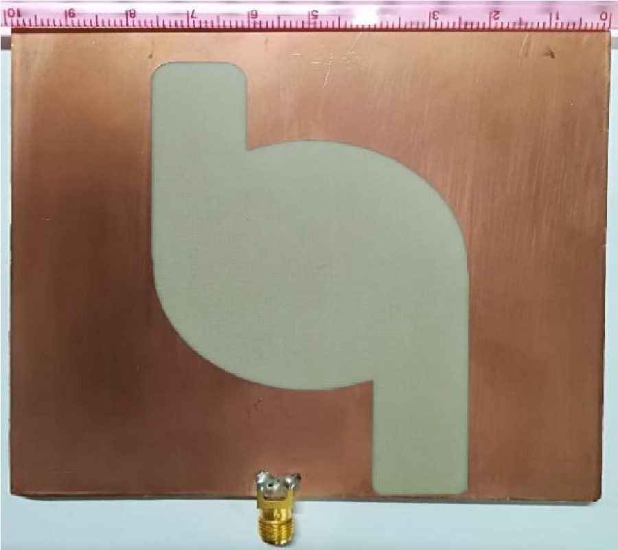
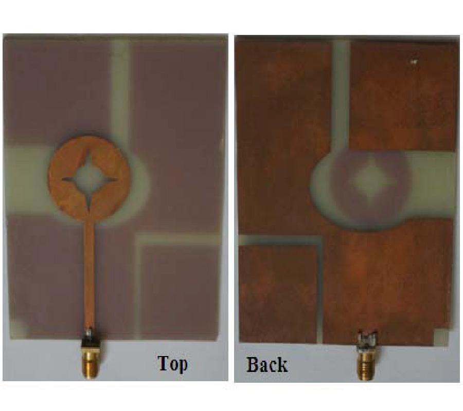
In this paper, a circularly polarized slot-patch antenna for nanosatellite is presented. The novel design of the circularly polarized wave conducted by two asymmetrical rectangular-truncation techniques implemented on a circularly-slotted-patch on the front side and a deformed-shifted-feedline on the back side of the substrate. The antenna is printed on substrates with the dielectric constant of 2.17 and thickness of 1.6 mm. The resonant frequency of the proposed antenna is set at 2.2 GHz with the minimum requirement of the axial ratio bandwidth (ARBW) of 300 MHz. The proposed antenna produces under -10 dB impedance bandwidth (IBW) 1.2765 GHz or equal to 58% (1.7235-3 GHz) with Left-Handed Circular Polarization (LHCP). The average antenna gain reaches 4.5 dBic at 2.2 GHz and the ARBW 327.5 MHz or about 14.88% (2.0275-2.355 GHz). This paper includes the description and presentation of the completed discussion.
A CIRCULARLY POLARIZED CIRCULARLY-SLOTTED-PATCH ANTENNA WITH TWO ASYMMETRICAL RECTANGULAR TRUNCATIONS FOR NANOSATELLITE ANTENNA
2019-03-05
PIER C
Vol. 90, 209-224, 2019
download: 311
Virtual Synchronous Motor Dynamic Power Decoupling Strategy
Xintian Liu , Yucai Li , Yao He , Xinxin Zheng and Guojian Zeng
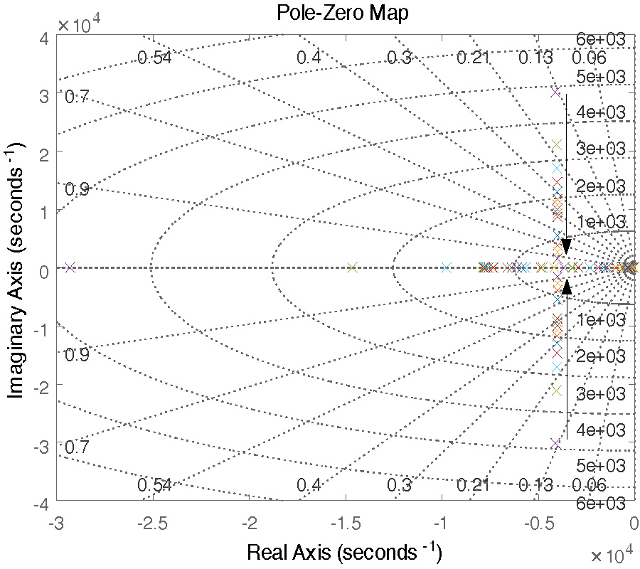
Due to the existence of power coupling the virtual synchronous motor (VSG) will lead to overshoot fluctuations in the power adjustment process, thus affecting the control performance. Compared to the traditional direct current control inverter based on coordinate transformation, VSG model is more complex and difficult to achieve decoupling. This paper presents a dynamic power decoupling method by studying the coupling relationship between active power and reactive power of VSG. Firstly, the inverter grid-connected model is established, and the power expression is analyzed when the inverter output impedance is negligible. Then the virtual active power and reactive power expressions are obtained through coordinate transformation. Several key state equations and virtual states of the VSG are obtained. The power expression performs small signal perturbation to obtain the dynamic model of the VSG. From this, the dynamic model of the VSG can be analyzed to obtain the coupling relationship between the dynamic powers, and the series power compensation is used to decouple the dynamic power coupling. Finally, the correctness of the theoretical analysis and the effectiveness of the decoupling method are verified by simulation and experiments.
VIRTUAL SYNCHRONOUS MOTOR DYNAMIC POWER DECOUPLING STRATEGY
2019-03-04
PIER C
Vol. 90, 195-208, 2019
download: 383
Theoretical and Experimental Investigation of Ferrite-Loaded Waveguide for Ferrimagnetism Characterization
Hsin-Yu Yao , Wei-Chen Chang , Li-Wen Chang and Tsun-Hun Chang
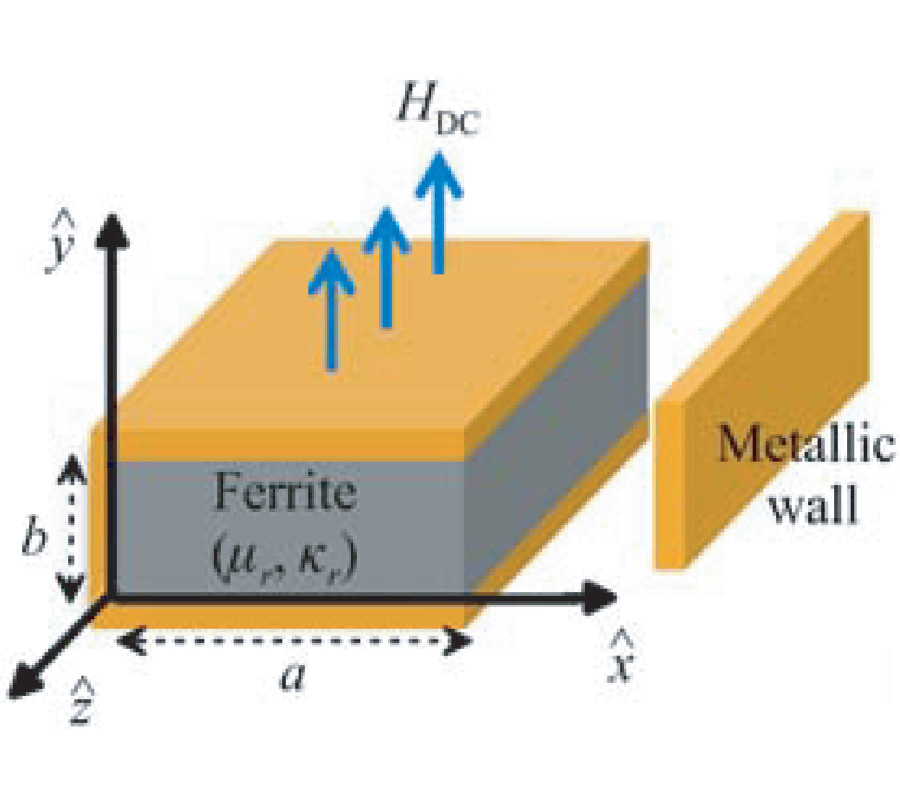
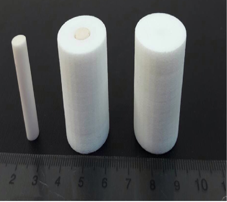
This work proposes an approach to retrieve the ferrite's electromagnetic properties in a single compact configuration, simpler than the traditional measurement systems. The ferrite under test is fully inserted into a rectangular waveguide with a magnetic bias. The complex scattering parameters are theoretically analyzed under the consideration of modal effect at isotropy-anisotropy interfaces. Extraordinarily sharp Fano resonances are observed in the scattering spectra, originating from the multimode interference inside the magnetized ferrite. There is good agreement among theoretical, experimental, and full-wave simulation results. This model can be further utilized to simultaneously retrieve all ferrite properties, including permittivity (ε), saturation magnetization (4πMs), and magnetic linewidth (ΔH) from the measured scattering parameters, facilitating the designs and applications of ferrite devices.
THEORETICAL AND EXPERIMENTAL INVESTIGATION OF FERRITE-LOADED WAVEGUIDE FOR FERRIMAGNETISM CHARACTERIZATION
2019-03-04
PIER C
Vol. 90, 183-193, 2019
download: 789
A Small Aperture Direction Finding System with Beamforming and Null Steering Capability
Sek-Meng Sow and Tan-Huat Chio
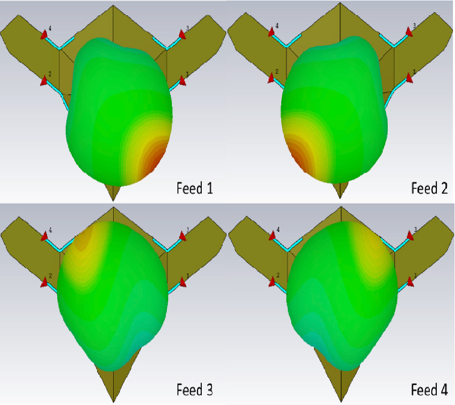
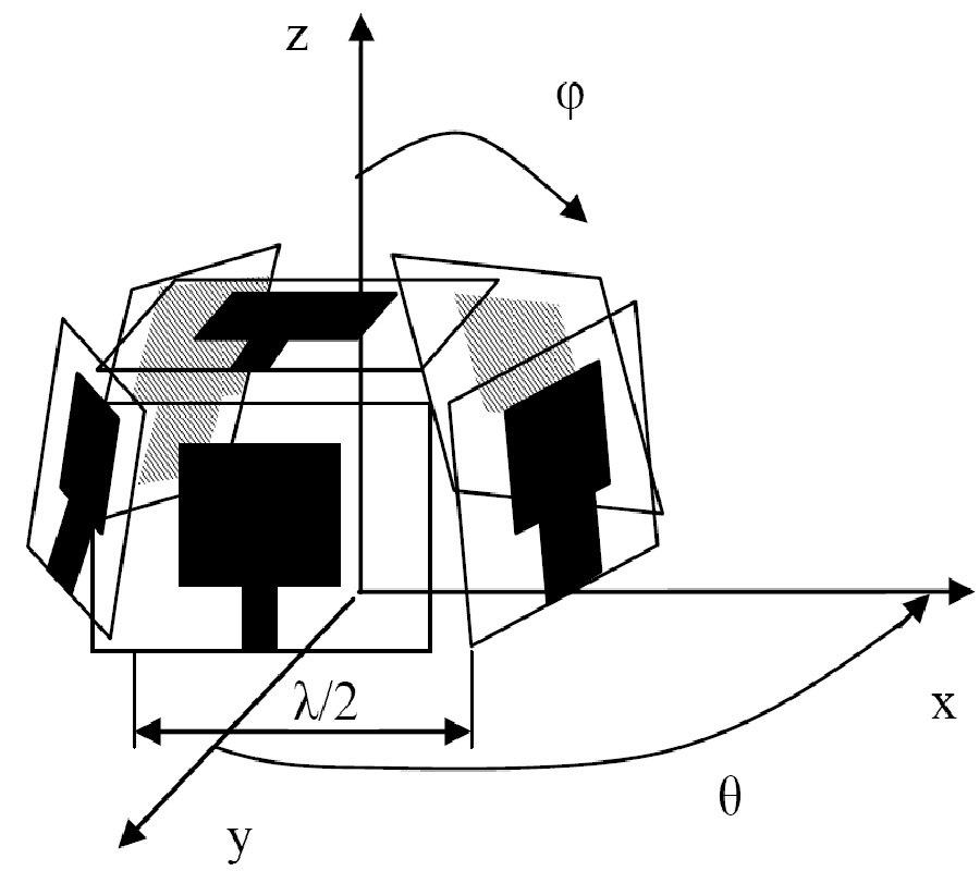
A Direction Finding (DF) algorithm for small aperture DF systems is proposed. Traditionally, small aperture DF systems lack of beamforming capabilities and therefore require manual rotation, which may affect the Angle of Arrival (AOA) estimation accuracy. Based on Characteristic Mode (CM) Analysis, a Multi-Feed Structural Antenna (MFSA) is developed that utilizes an electrically small platform as a radiator. This paper chooses a Small Unmanned Aerial Vehicle (SUAV) as a design platform. The overlap of all Individual Element Radiation Patterns (IERPs) of the proposed MFSA covers the entire azimuth plane. In this way, beamforming and null steering of the MFSA on the azimuth plane can be achievedby linearly combining all weighted IERPs. A new method based on Vector Singular Value Decomposition (SVD) is proposed to determine the weight vector of beamforming (``Sum'' pattern) and null steering (``Difference'' pattern) in a specific direction. Based on the ``Sum-Difference'' delta method, the AOA of the Radio Frequency (RF) signal source can be estimated. A small aperture VHF DF system with a multi-channel digital-IF receiver is developed to experimentally verify the proposed concept. The evaluation results show that the AOA estimation RMS error is 1.55°, and the false detection rate is significantly improved.
A SMALL APERTURE DIRECTION FINDING SYSTEM WITH BEAMFORMING AND NULL STEERING CAPABILITY
2019-03-01
PIER C
Vol. 90, 169-181, 2019
download: 764
A CMOS Power Amplifier Using a Balun Embedded Driver Stage for IEEE 802.11N WLAN Applications
Minoh Son , Jinho Yoo , Changhyun Lee and Changkun Park
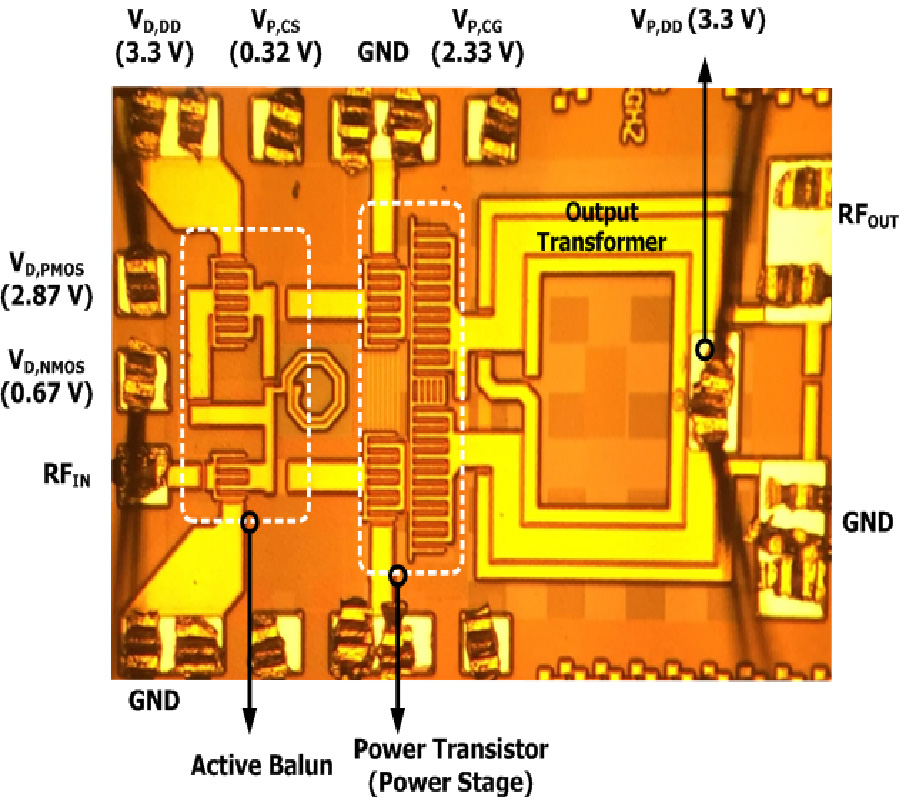
In this work, we propose a balun embedded driver stage to enhance the bandwidth and minimize the chip size of a differential CMOS power amplifier. By removing the passive input transformer, the bandwidth and chip size are improved. The proposed driver stage acts as an input balun as well as the driver stage for the power stage. The proposed driver is composed of a cascade connected PMOS, an inductor, and NMOS to generate the differential output signal. For the function of the input balun, the gate of the PMOS is connected to the drain of the NMOS. To verify the feasibility of the proposed balun embedded driver stage, we design a differential CMOS power amplifier for 5-GHz IEEE 802.11n WLAN applications. The designed power amplifier is fabricated using the 180-nm SOI RF CMOS process. The measured 3-dB bandwidth is approximately 2.5 GHz. The chip size of the fully integrated power amplifier, including input and output matching networks and test pads, is 0.885 mm2. The measured maximum output power is 20.18 dBm with a PAE of 10.16%.
A CMOS POWER AMPLIFIER USING A BALUN EMBEDDED DRIVER STAGE FOR IEEE 802.11N WLAN APPLICATIONS
2019-03-01
PIER C
Vol. 90, 155-167, 2019
download: 374
Design Analysis of a Semi-Circular Floral Shaped Directional UWB Antenna Integrated with Wireless Multiband Applications
Madan Lal Meena and Asheesh Gupta
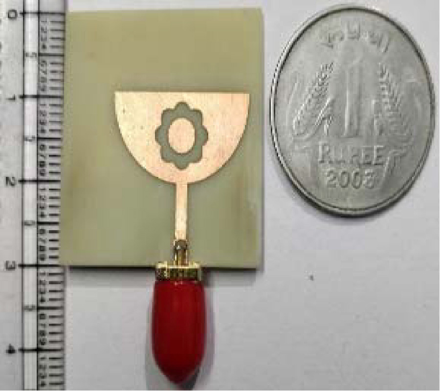
This work presents a novel structure of semi-circular floral shape slotted antenna for an ultra-wideband (UWB) including WCDMA, Bluetooth and Wi-Max applications. Initially, a semi-circular floral shape radiator is designed by inserting an elliptical slot in patch with partial rectangular ground plane. Further, three rectangle symmetrical stepped slots are inserted in ground below 50 ohm micro-strip (MS) feed line which is integrated with stepped quarter wave transformer to achieve an ultra-wide impedance bandwidth. The proposed antenna structure achieves UWB of 4-18 GHz which cover 127% (S11<-10 dB) fractional bandwidth (FBW). Furthermore, ground plane is modified by loading three asymmetrical capacitive folded strip resonators (CFSR), which provide an additional lower frequency communication bands 2100 MHz (2-2.2 GHz), 2400 MHz (2.34-2.47 GHz), and 2700 MHz (2.69-2.75 GHz) for applications of WCDMA, Bluetooth, and Wi-Max, respectively. An optimized dimension of the proposed antenna is 30×30 mm2 (1.1λ0 ×1.1λ0), which is designed and fabricated on an FR-4 substrate having thickness 1.6 mm and dielectric constant 4.3. The proposed design is computed by Electromagnetic (EM), ADS simulator, and simulation results are validated with measured results.
DESIGN ANALYSIS OF A SEMI-CIRCULAR FLORAL SHAPED DIRECTIONAL UWB ANTENNA INTEGRATED WITH WIRELESS MULTIBAND APPLICATIONS
2019-02-28
PIER C
Vol. 90, 139-154, 2019
download: 458
Evaluation and Minimization of Cramer-Rao Bound for Conformal Antenna Arrays with Directional Emitters for DOA-Estimation
Yuri Nechaev , Ilia Peshkov and Natalia Fortunova
The Cramer-Rao lower bound (CRLB) for calculating errors and accuracy of direction-of-arrival (DOA) estimation is discussed for a number of planar waves arriving on an antenna array. It is well known that the geometry of antenna arrays imposes restrictions on the performances of the direction-of-arrival estimation. In particular, the influence of the directivity factor of the individual antenna elements on the accuracy of the DOA estimation of the radio emission sources for circular (cylindrical), cubic and spherical antenna arrays consisting of the directional antenna elements is investigated. The directivity factor of antenna elements is changed within wide limits in order to determine the values at which the high accuracy of the direction-finding can be achieved. It is shown that further increasing the directivity factor of each antenna element makes the mean square error in the determination of the coordinates of the signals increase as well. The exact expression for the Cramer-Rao lower bound for the DOA-estimation variance calculation depending on the antenna directivity and the geometry is presented. The obtained exact equation shows the most important factors that the direction-of-arrival estimation accuracy is dependent on. A technique of obtaining antenna arrays with optimal directional elements locations is proposed. Those arrays allow increasing DOA estimation accuracy by several times.
EVALUATION AND MINIMIZATION OF CRAMER-RAO BOUND FOR CONFORMAL ANTENNA ARRAYS WITH DIRECTIONAL EMITTERS FOR DOA-ESTIMATION
2019-02-28
PIER C
Vol. 90, 125-138, 2019
download: 551
A Wide-Beam Base Station Antenna with Modular Radiator for Reconfigurability
Joshua W. Shehan and Ryan S. Adams
This paper presents a reconfigurable, wide-beam antenna with a modular main radiator for base station applications. The addition of new spectrum and the path to 5G create unique antenna requirements in terms of patterns and impedance matching capabilities. The antenna in this paper exhibits a wide azimuth beamwidth up to approximately 180o, and implements a modular approach where the antenna can be recon gured for impedance matching requirements. Two con gurations of the wide-beam antenna are presented; the rst con guration covers the 1.7-2.7 GHz band for 3G/4G/LTE applications where multiple wireless carriers would use the same antenna as a neutral site. This antenna provides wide-beam operation and a 10-dB return loss from approximately 1.64-2.76 GHz. The measured return loss over the 1.7-2.7 GHz band is better than 13 dB. A second con guration of the antenna is tuned for performance from 1.9-2.4 GHz where measured return loss better than 19 dB is achieved in this band. Simulated and measured return losses and patterns are presented that show very good agreement between simulation and measurement, and thorough parametric pattern analysis is presented for the baseline antenna configuration.
A WIDE-BEAM BASE STATION ANTENNA WITH MODULAR RADIATOR FOR RECONFIGURABILITY
2019-02-27
PIER C
Vol. 90, 109-124, 2019
download: 365
Spherical Mapping of the Second-Order Phoenix Cell for Unbounded Direct Reflectarray Copolar Optimization
Vincent Richard , Renaud Loison , Raphael Gillard , Hervé Legay , Maxime Romier , Jean-Paul Martinaud , Daniele Bresciani and Fabien Delepaux
A general synthesis approach is proposed for reflectarrays using second order Phoenix cells. It relies on an original spherical representation that transforms the optimization domain in a continuous and unbounded space with reduced dimension. This makes the synthesis problem simpler and automatically guarantees smooth variations in the optimized layout. The proposed mapping is combined with an Artificial Neural Network (ANN) based behavioral model of the cell and integrated in a min/max optimization process. Bi-cubic spline expansions are used to decrease the number of variables. As an application, a contoured beam for space communication in the [3.6-4.2] GHz band is considered. The gain improvement compared to an initial Phase Only synthesis (POS) is up to 1.62 dB at the upper frequency. Full wave simulation of the final array is provided as a validation.
SPHERICAL MAPPING OF THE SECOND-ORDER PHOENIX CELL FOR UNBOUNDED DIRECT REFLECTARRAY COPOLAR OPTIMIZATION
2019-02-27
PIER C
Vol. 90, 95-107, 2019
download: 275
A Novel Design of Hybrid Open Slot Antenna with Parasitic Element for Wideband Applications
Prashant Purohit , Bhupendra Kumar Shukla and Deepak Kumar Raghuvanshi
In this communication, a novel design of a hybrid open slot antenna is investigated and experimentally verified. The proposed structure comprises a slotted tuning stub, a proximity fed parasitic element, and slotted ground plane. Tuning and overlapping of best matching frequencies fr1, fr2, fr3, fr4, fr5, fr6, and fr7 are accomplished by varying the dimension of the parasitic element and elliptical slot which is the part of the elliptical slot. The experimental results reveal that this antenna covers the fractional bandwidth (BW(%) = 200 * (fh - fl)/(fh + fl)) of 139.5% from 0.98 GHz to 5.5 GHz for |S11|<-10 dB which is suitable for GSM 1800, WiMAX, PCS, and ITM-2000. After the analysis of current distribution, mathematical equations are developed for frequencies 1.04, 1.52, 3.06, 3.67, and 4.58 GHz. The structural analysis is also carried out for optimization and to know the electromagnetic behaviour of the antenna. Asymmetric radiation patterns are found at resonating frequencies due to open slot geometry.
A NOVEL DESIGN OF HYBRID OPEN SLOT ANTENNA WITH PARASITIC ELEMENT FOR WIDEBAND APPLICATIONS
2019-02-20
PIER C
Vol. 90, 79-93, 2019
download: 336
Radar Scatter from Layered Media and Rough Surfaces
Pradeep Bobby and Eric W. Gill
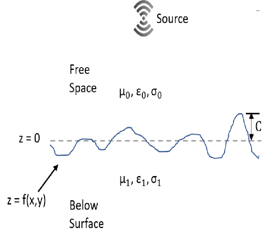
The generalized function approach for modeling radio wave scattering has been used to develop expressions for the scatter from rough surfaces and for horizontally-stratified media. The scattered field from rough surfaces can be found in closed form if plane wave incidence is assumed, but the method is valid for any realizable source without resorting to using Hertz vectors. This approach was originally developed to model high frequency surface wave radar scattering from the ocean or across layers of ice covering the ocean using vertical polarization. This paper presents three extensions to the existing theory: the x component of the scattered field for rough surface scattering is developed, the assumption of a good conducting surface assumption is removed for a rough surface and the scatter from stratified media is simplified in terms of a scattering coefficient. The shape of the scattered field is not affected by the relative permittivity, but the intensity of the scattered field is weaker due to an increased transmission of energy through the surface. The goal for this research is to better understand how signatures from ice-penetrating radar can be used to distinguish hazardous ice ridges from other ice features. Here, ice ridges are modeled as layered media with a rough surface.
RADAR SCATTER FROM LAYERED MEDIA AND ROUGH SURFACES
2019-02-19
PIER C
Vol. 90, 65-77, 2019
download: 455
Higher Order Mode Layered Cylindrical Dielectric Resonator Antenna
Abdulmajid A. Abdulmajid and Salam Khamas
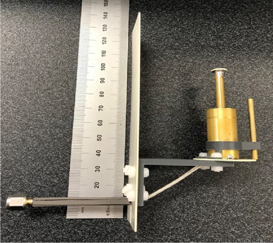
A wideband high gain circularly polarized layered cylindrical dielectric resonator antenna (DRA) that operates in a higher order mode is proposed in the X-band frequency range. The antenna consists of two dielectric layers having different dielectric constants and radii. The results demonstrate a considerably improved performance as a result of adding the outer dielectric layer, where wider impedance and axial ratio bandwidths have been attained in conjunction with a higher broadside gain of ~14 dBic. A prototype has been built and measured with close agreement between experimental and simulated results.
HIGHER ORDER MODE LAYERED CYLINDRICAL DIELECTRIC RESONATOR ANTENNA
2019-02-11
PIER C
Vol. 90, 51-63, 2019
download: 297
A New Fast and Accurate Compressive Sensing Technique for Magnetic Resonance Imaging
Huihui Yue and Xiangjun Yin
In this paper, the main problem to be solved is how to achieve magnetic resonance imaging (MRI) accurately and quickly. Previous work has shown that compressive sensing (CS) technology can reconstruct a magnetic resonance (MR) image from only a small number of samples, which significantly reduces MR scanning time. Based on this, an algorithm to improve the accuracy of MRI, called regularized weighting Composite Gaussian smoothed l0-norm minimization (RWCGSL0), is proposed in this paper. Different from previous methods, our algorithm has three influential contributions: (1) a new smoothed Composite Gaussian function (CGF) is proposed to be closer to the l0-norm; (2) a new weighting function is proposed; (3) a new l0 regularized objective function framework is constructed. Furthermore, the optimal solution of this objective function is obtained by penalty decomposition (PD)method. It is experimentally shown that the proposed algorithm outperforms other state-of-the-art CS algorithms in the reconstruction of MR images.
A NEW FAST AND ACCURATE COMPRESSIVE SENSING TECHNIQUE FOR MAGNETIC RESONANCE IMAGING
2019-01-30
PIER C
Vol. 90, 41-49, 2019
download: 397
Design of Compact, Wideband Dual-Polarized Multi-Dipole Antenna for 2G/3G/LTE Base Station Applications
Zhaoyang Tang , Yapeng Li , Zhipeng Zhao and Ying-Zeng Yin
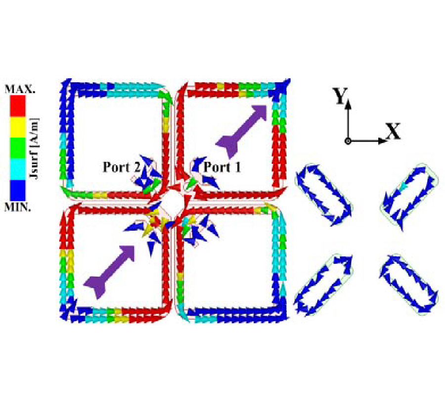
In this paper, awideband dual-polarized multi-dipole antennawith a compact radiator size is developedfor 2G/3G/LTE base station applications. The original antenna is composed of a pair of crossed square loop dipoles (SLDs) and two big Y-shaped feeding lines. Thanks to the adopted capacitive coupling, a wide impedance bandwidth is obtained with dual resonant modesin the low and middle frequency bands. Owing to the circular chamfersin thecrossed SLDs, the dual resonant modes are away from each other. Thus, a compact radiator size is implemented, and it is about 0.382λ0×0.382λ00 is the wavelength at center frequency of operation). To further widen the operating bandwidth of the antenna, a pair of crossed rectangular loop dipoles (RLDs) and four small Y-shaped feeding lines are introduced to generate a new resonant mode at high frequency. As a result, the impedance bandwidth of the proposed antenna is enhanced.Based on the optimized dimensions of the simulated antenna model, a prototype is developed, fabricated and tested. Measured results show that the proposed antenna has a relative impedance bandwidth of 53.9% from 1.68 to 2.92 GHz at two ports for VSWR<1.5. Within the operating impedance bandwidth, the measured port-to-port isolation is better than 30 dB. In addition, a stable gain of 8.2±0.5 dBi and a stable radiation pattern with 66°±4° half-power beamwidth (HPBW) in the horizontal plane are achieved across the whole bandwidth of operationfor dual polarizations. Finally, the proposed antenna is suitable for base station applications.
DESIGN OF COMPACT, WIDEBAND DUAL-POLARIZED MULTI-DIPOLE ANTENNA FOR 2G/3G/LTE BASE STATION APPLICATIONS
2019-01-14
PIER C
Vol. 90, 29-39, 2019
download: 396
A Novel Dual-Passband Net-Shaped FSS Structure Used for MIMO Antennas
Zhiwei Liu , Shunli Jie , Haitao Ma , Xiao-Yan Zhang and Beibei Xing
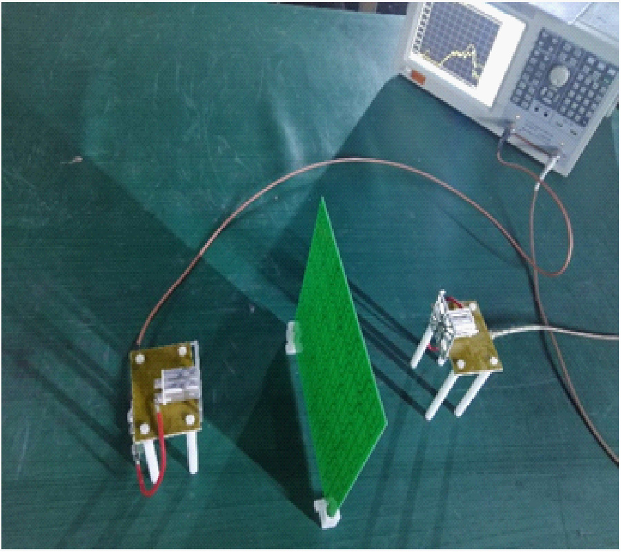
A dual-passband frequency selective surface (FSS) is designed in this paper. Two passbands are 2-3.4 GHz and 5.5-6.8 GHz, respectively. It is used as a spatial filter to improve the radiation and scattering performance of an antenna. The structure is combined with two layers. One is metal, and the other is intermediate medium. The requirements of wide-band, polarization-independent, wide incidence angle and miniaturized FSS with a thickness of only 0.0085λ are achieved by parameter optimization. When the FSS is used to improve the proposed microstrip antenna, the relative bandwidth can be increased by 31.4% and 50%, and the peak gain is increased by 2.53 dB and 1.86 dB at 5.8 GHz and 6.4 GHz, respectively. Meanwhile, the maximum RCS reduction of the microstrip antenna is 16 dB. On the other hand, the FSS is able to be applied to a dipole antenna to improve the transmission coefficient and phase. Simulation and measurement results of the transmission coefficient and phase of the antenna are almost the same.
A NOVEL DUAL-PASSBAND NET-SHAPED FSS STRUCTURE USED FOR MIMO ANTENNAS
2019-01-10
PIER C
Vol. 90, 15-28, 2019
download: 428
Design and Manufacturing of a Novel Compact 2.4 GHz LPF Using a DGS-DMS Combination and Quasi Octagonal Resonators for Radar and GPS Applications
Ahmed Boutejdar , Mouloud Challal , Sudipta Das and Soumia El Hani
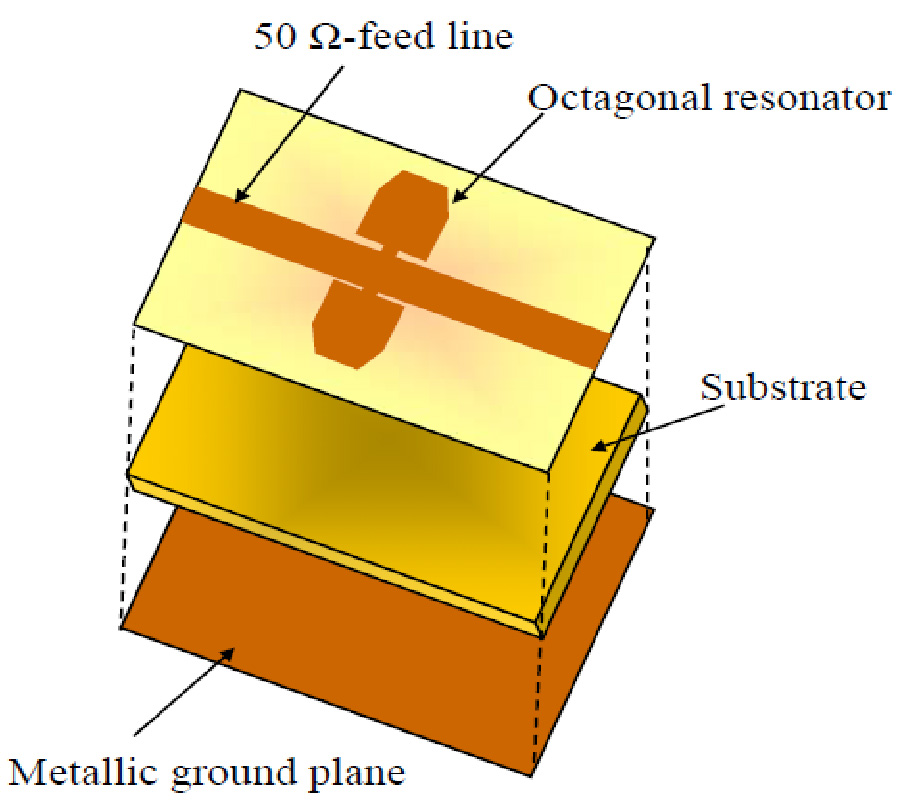
In this paper, a new compact microstrip low-pass filter (LPF) with ultra-wide stopband characteristics is presented. The combinations of DGS-DMS along with quasi octagonal resonators are employed in the design of the proposed filter to achieve compact size and ultra-wide stopband suppression level. The proposed filter has been designed, simulated, optimized and tested. The design procedure is validated using the commercial full-wave EM MoM simulator Microwave Office. Simulated as well as measured results of low-pass filter exhibit sharp roll-off (ξ) of 19 dB/GHz and creating transmission zero at around 7.8 GHz with attenuation level -54 dB. The measurement results show good agreement with the simulations. The cutoff frequency of the proposed low-pass filter is 2.4 GHz with the insertion loss less than 0.3 dB. The ultra wide stop band with over 20 dB attenuation extended from 3.42 GHz to 12 GHz. The spurious passband suppression up to six harmonics (5fc) is achieved for the proposed design. The addition of two parasitics DGS elements in the ground plane leads to suppression of the undesired harmonics and thus to improve the stopband. The size of the whole structure is less as (0.44λgx0.26λg) with λg = 68 mm. The proposed filter is useful for microwave L band, GPS system, and RADAR applications.
DESIGN AND MANUFACTURING OF A NOVEL COMPACT 2.4 GHZ LPF USING A DGS-DMS COMBINATION AND QUASI OCTAGONAL RESONATORS FOR RADAR AND GPS APPLICATIONS
2019-01-05
PIER C
Vol. 90, 1-13, 2019
download: 331
Double-Port Slotted-Antenna with Multiple Miniaturized Radiators for Wideband Wireless Communication Systems and Portable Devices
Mohammad Alibakhshikenari , Mohsen Khalily , Bal Singh Virdee , Abdul Ali , Panchamkumar Shukla , Chan Hwang See , Raed A. Abd-Alhameed , Francisco J. Falcone and Ernesto Limiti
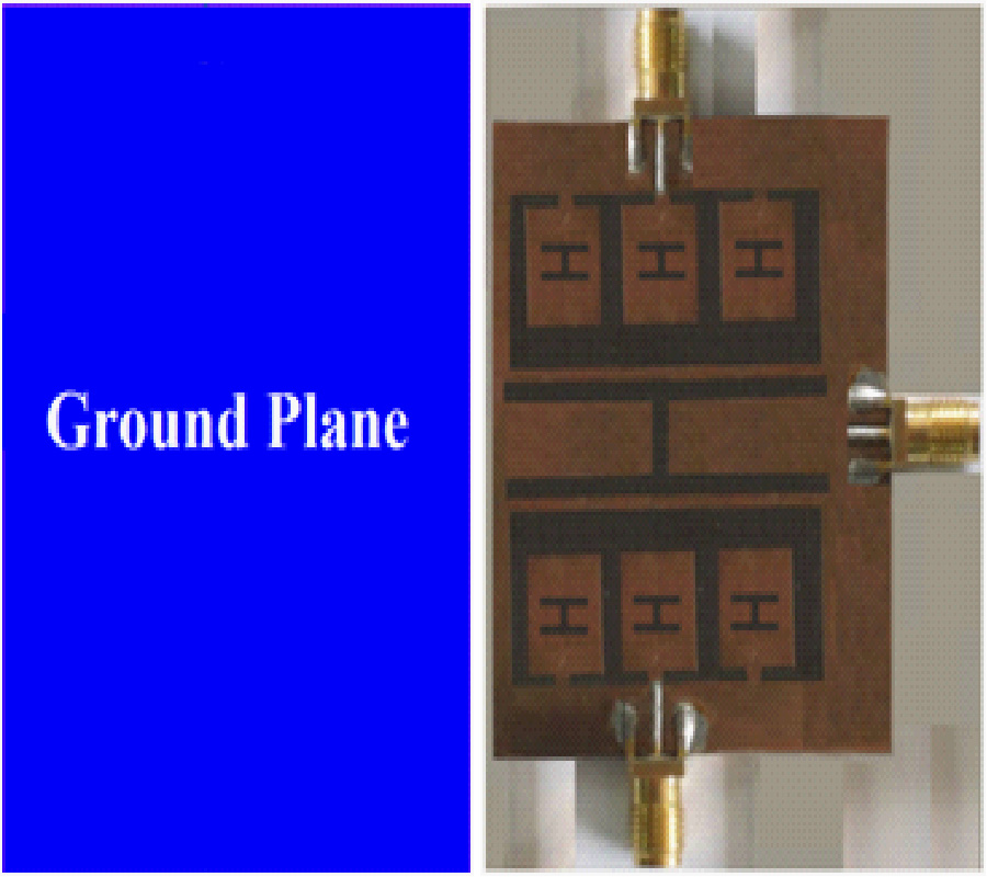
Proof-of-concept is presented of a novel slot antenna structure with two excitation ports. Although this antenna provides a wide impedance bandwidth, its peak gain and optimum radiation efficiency are observed at its mid-band operational frequency. The antenna structure is etched on the top side of a dielectric substrate with a ground plane. The antenna essentially consists of a rectangular patch with two dielectric slots in which multiple coupled patch arms embedded with H-shaped slits are loaded. The two dielectric slots are isolated from each other with a large H-shaped slit. The radiation characteristics of the proposed antenna in terms of impedance bandwidth, gain and efficiency can be significantly improved by simply increasing the number of radiation arms and modifying their dimensions. The antenna's performance was verified by building and testing three prototype antennas. The final optimized antenna exhibits a fractional bandwidth of 171% (0.5-6.4 GHz) with a peak gain and maximum radiation efficiency of 5.3 dBi and 75% at 4.4 GHz, respectively. The antenna has physical dimensions of 27×37×1.6 mm3 corresponding to electrical size of 0.0452λ0×0.0627λ0×0.0026λ0, where λ0 is free-space wavelength at 0.5 GHz. The antenna is compatible for integration in handsets and other broadband wireless systems that operate over L-, S-, and C-bands.
DOUBLE-PORT SLOTTED-ANTENNA WITH MULTIPLE MINIATURIZED RADIATORS FOR WIDEBAND WIRELESS COMMUNICATION SYSTEMS AND PORTABLE DEVICES