Vol. 112
Latest Volume
All Volumes
PIERC 149 [2024] PIERC 148 [2024] PIERC 147 [2024] PIERC 146 [2024] PIERC 145 [2024] PIERC 144 [2024] PIERC 143 [2024] PIERC 142 [2024] PIERC 141 [2024] PIERC 140 [2024] PIERC 139 [2024] PIERC 138 [2023] PIERC 137 [2023] PIERC 136 [2023] PIERC 135 [2023] PIERC 134 [2023] PIERC 133 [2023] PIERC 132 [2023] PIERC 131 [2023] PIERC 130 [2023] PIERC 129 [2023] PIERC 128 [2023] PIERC 127 [2022] PIERC 126 [2022] PIERC 125 [2022] PIERC 124 [2022] PIERC 123 [2022] PIERC 122 [2022] PIERC 121 [2022] PIERC 120 [2022] PIERC 119 [2022] PIERC 118 [2022] PIERC 117 [2021] PIERC 116 [2021] PIERC 115 [2021] PIERC 114 [2021] PIERC 113 [2021] PIERC 112 [2021] PIERC 111 [2021] PIERC 110 [2021] PIERC 109 [2021] PIERC 108 [2021] PIERC 107 [2021] PIERC 106 [2020] PIERC 105 [2020] PIERC 104 [2020] PIERC 103 [2020] PIERC 102 [2020] PIERC 101 [2020] PIERC 100 [2020] PIERC 99 [2020] PIERC 98 [2020] PIERC 97 [2019] PIERC 96 [2019] PIERC 95 [2019] PIERC 94 [2019] PIERC 93 [2019] PIERC 92 [2019] PIERC 91 [2019] PIERC 90 [2019] PIERC 89 [2019] PIERC 88 [2018] PIERC 87 [2018] PIERC 86 [2018] PIERC 85 [2018] PIERC 84 [2018] PIERC 83 [2018] PIERC 82 [2018] PIERC 81 [2018] PIERC 80 [2018] PIERC 79 [2017] PIERC 78 [2017] PIERC 77 [2017] PIERC 76 [2017] PIERC 75 [2017] PIERC 74 [2017] PIERC 73 [2017] PIERC 72 [2017] PIERC 71 [2017] PIERC 70 [2016] PIERC 69 [2016] PIERC 68 [2016] PIERC 67 [2016] PIERC 66 [2016] PIERC 65 [2016] PIERC 64 [2016] PIERC 63 [2016] PIERC 62 [2016] PIERC 61 [2016] PIERC 60 [2015] PIERC 59 [2015] PIERC 58 [2015] PIERC 57 [2015] PIERC 56 [2015] PIERC 55 [2014] PIERC 54 [2014] PIERC 53 [2014] PIERC 52 [2014] PIERC 51 [2014] PIERC 50 [2014] PIERC 49 [2014] PIERC 48 [2014] PIERC 47 [2014] PIERC 46 [2014] PIERC 45 [2013] PIERC 44 [2013] PIERC 43 [2013] PIERC 42 [2013] PIERC 41 [2013] PIERC 40 [2013] PIERC 39 [2013] PIERC 38 [2013] PIERC 37 [2013] PIERC 36 [2013] PIERC 35 [2013] PIERC 34 [2013] PIERC 33 [2012] PIERC 32 [2012] PIERC 31 [2012] PIERC 30 [2012] PIERC 29 [2012] PIERC 28 [2012] PIERC 27 [2012] PIERC 26 [2012] PIERC 25 [2012] PIERC 24 [2011] PIERC 23 [2011] PIERC 22 [2011] PIERC 21 [2011] PIERC 20 [2011] PIERC 19 [2011] PIERC 18 [2011] PIERC 17 [2010] PIERC 16 [2010] PIERC 15 [2010] PIERC 14 [2010] PIERC 13 [2010] PIERC 12 [2010] PIERC 11 [2009] PIERC 10 [2009] PIERC 9 [2009] PIERC 8 [2009] PIERC 7 [2009] PIERC 6 [2009] PIERC 5 [2008] PIERC 4 [2008] PIERC 3 [2008] PIERC 2 [2008] PIERC 1 [2008]
2021-05-18
PIER C
Vol. 112, 251-261, 2021
download: 369
Triangular Shaped QMSIW Cavity Back Slot Antenna for Tri-Band Operation
Dokuparthi Jagadeesh and Alapati Sudhakar
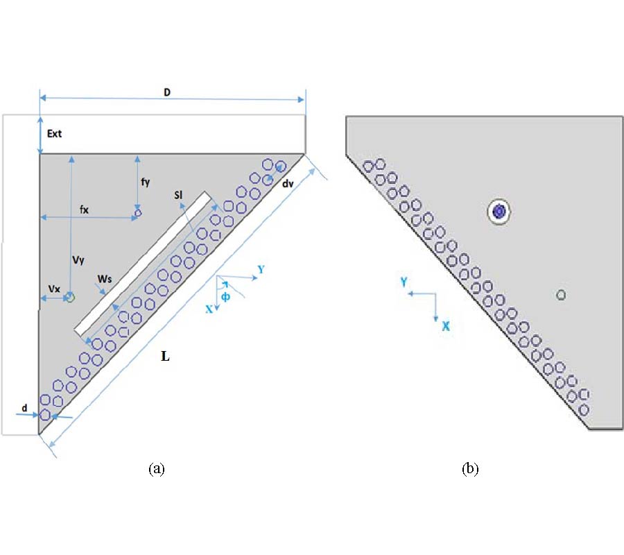
In this paper, a triangle-shaped Quarter Mode Substrate Integrated Waveguide (QMSIW) cavity back slot antenna is developed using TE110, TE220, and TE310, 130 modes for tri-band operation. The QMSIW is obtained from the quadrant part of a square SIW (Substrate Integrated Waveguide) structure. The electric field distributions of resonant modes are studied for the Full Mode SIW, Half Mode SIW, and Quarter Mode SIW cavities through HFSS simulation tool. The generation of the hybrid mode TE310, 130 mode is clearly explained with the simulation tool. A rectangular slot is engraved on top layer of the structure along the perfect electric wall, to radiate the EM (Electro Magnetic) wave towards positive Z-direction. Further, a metallized via has been inserted to bring reflection coefficient below -10 dB at the three resonant modes. The developed antenna achieves resonance at 5.2 GHz, 9.88 GHz, and 10.6 GHz frequencies with peak gains of 9 dB, 6.2 dB, and 7.9 dB, respectively. The antenna is designed on a single layer thin substrate which reduces the fabrication complexity.
TRIANGULAR SHAPED QMSIW CAVITY BACK SLOT ANTENNA FOR TRI-BAND OPERATION
2021-05-18
PIER C
Vol. 112, 239-250, 2021
download: 458
A Comparative Study of Some Novel Wideband Tulip Flower Monopole Antennas with Modified Patch and Ground Plane
Nurhayati Nurhayati , Alexandre Manicoba de Oliveira , Warangkana Chaihongsa , Bagus Edy Sukoco and Akbar Kurnia Saleh
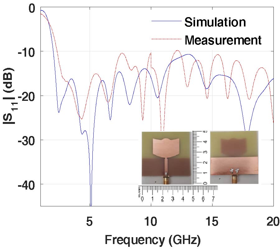
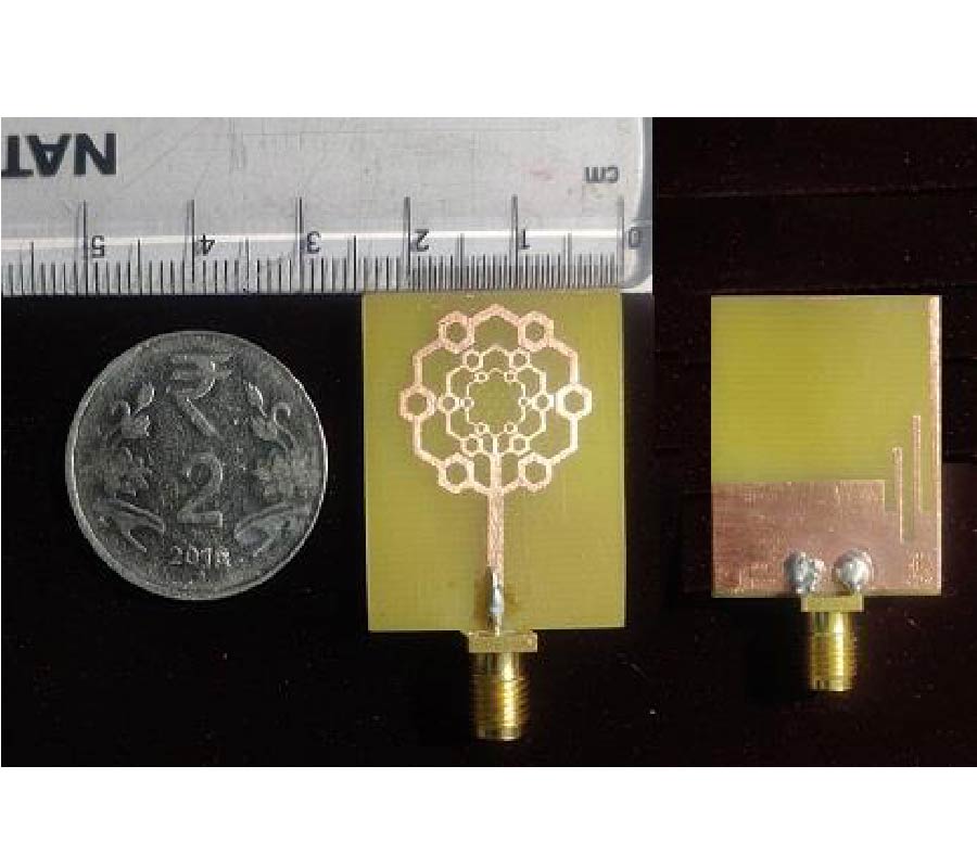
Comparative study of some novel wideband Tulip Flower Monopole Antennas (TFMAs) is presented in this paper. To Improve the bandwidth and increase the gain, modification of the shape of the curves and slots in the patch and ground plane was carried out on the seven TFMAs. TFMA-A, TFMA-B, TFMA-C, and TFMA-D have dimensions of 50×50 mm2, while TFMA-E, TFMA-F, and TFMA-G have dimensions of 30×70 mm2. From the simulation result, TFMA-A operated from 2 GHz to more than 30 GHz with a return loss of 15 dB occupies most of its operating frequency. In the whole frequency work, the peak directivity performance in the order of superiority is obtained for TFMA-G, TFMA-F, TFMA-D, TFMA-E, TFMA-C, TFMA-B, and TFMA-A. The improvement of directivity is reached for TFMA-D of 5.03 if it is compared to TFMA-A at 24 GHz. TFMA-G obtains the peak of directivity of 10.148 dBi at 23 GHz. The impedance bandwidth and directivity of the antenna element change by varying the curvature, the shape, and the position of slot in the radiator and ground plane also the height of the microstrip feeding line and ground plane. The return losses of the TFMA-A and TFMA-E show good agreement between simulation and measurement results.
A COMPARATIVE STUDY OF SOME NOVEL WIDEBAND TULIP FLOWER MONOPOLE ANTENNAS WITH MODIFIED PATCH AND GROUND PLANE
2021-05-17
PIER C
Vol. 112, 221-238, 2021
download: 473
Compact-Size Quad-Band Patch and MIMO Antenna System for 5G Mobile Handsets
May Abd Elazeem Abo-Elhassan , Asmaa Elsayed Farahat and Khalid Fawzy Ahmed Hussein
A compact-size quad-band (28/45/51/56 GHz) microstrip patch antenna is proposed for the Fifth Generation (5G) mobile handsets. The present paper introduces a new method to reduce the size of a 28-GHz rhombic patch antenna so as to properly operate at the higher frequency bands (45/51/56 GHz) without negative effects on the antenna characteristics at 28 GHz. A novel design is introduced for the quad-band patch antenna to include complicated radiation mechanisms required for multiple-band operation. The proposed (single-element) antenna is constructed as primary and secondary patches which are capacitively coupled and designed to realize impedance matching and to produce appropriate radiation patterns in the four frequency bands. Two-port and four-port MIMO antenna systems that employ the quad-band patch antenna are proposed in the present work for the 5G mobile handsets. Numerical and experimental investigations are achieved to assess the performance of both the single-element antenna and the proposed MIMO antenna systems including the return loss at each antenna port and the coupling coefficients between the different ports. It is shown that the simulation results agree with the experimental measurements, and both show good performance. The bandwidths achieved around 28, 45, 51, and 56 GHz are about 0.6, 2.0, 1.8, and 1.3 GHz, respectively. The radiation patterns produced when each port is excited alone are shown to be suitable for spatial diversity scheme with high radiation efficiency. It is shown that the envelope correlation coefficient (ECC) and diversity gain (DG) are perfect over the four frequency bands.
COMPACT-SIZE QUAD-BAND PATCH AND MIMO ANTENNA SYSTEM FOR 5G MOBILE HANDSETS
2021-05-16
PIER C
Vol. 112, 207-219, 2021
download: 738
A High Isolation Multiband MIMO Antenna Without Decoupling Structure for WLAN/WiMAX /5G Applications
Dhanasekaran Dileepan , Somasundaram Natarajan and Rengasamy Rajkumar
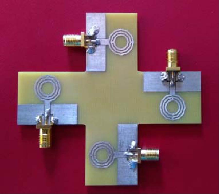
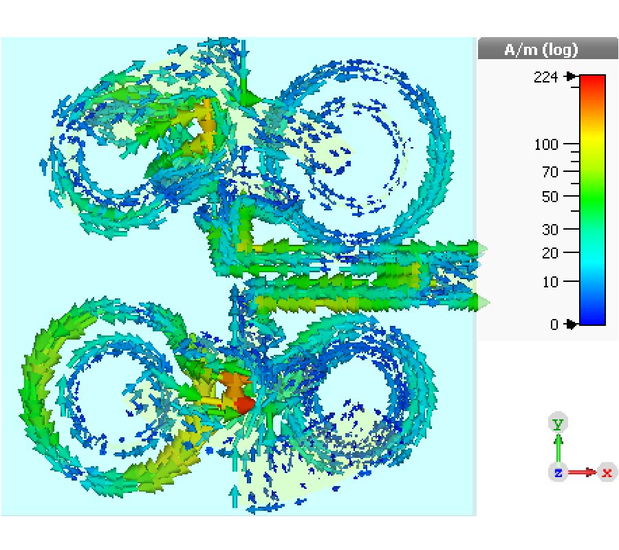
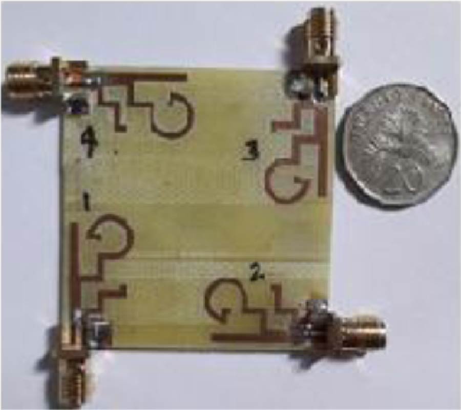
In this paper, 1 × 1 and 2 × 2 Multiple-input Multiple-output (MIMO) antenna is designed for a multiband application. The antenna consists of three concentrated decagon shaped rings which are responsible for obtaining the three resonance frequencies. The proposed antenna has a unique design technique; without using any decoupling structure the antenna attains better isolation performance. First, a two (1 × 1) element MIMO antenna with three different orientations (Orientation-I, II, and III) is studied. Second, a four-element MIMO antenna is designed without any decoupling structure for better performance. The above two antenna designs are fabricated and measured. The dimension of the proposedantenna element is 23.5 mm × 26.5 mm, and it has -10 dB impedance bandwidth over 2.4-2.52 GHz, 3.66-4 GHz, and 4.62-5.54 GHz, which cover various applications such as WLAN (2.4/5.2 GHz), WiMAX (2.5/5.5 GHz), public safety (4.9 GHz), and 5G (3.6-3.8 GHz). The proposed MIMO antenna diversity performances such as isolation, ECC, Directivity Gain, TARC, Channel Capacity Loss (CCL), and Mean Effective Gain (MEG) are studied.
A HIGH ISOLATION MULTIBAND MIMO ANTENNA WITHOUT DECOUPLING STRUCTURE FOR WLAN/WIMAX/5G APPLICATIONS
2021-05-12
PIER C
Vol. 112, 193-205, 2021
download: 389
Compact Quad-Port High Performance UWB MIMO/Diversity Antenna with Slotted Ground Structure
Pankaj Kumar Keshri , Richa Chandel , Sanjay Kumar Sahu and Anil Kumar Gautam
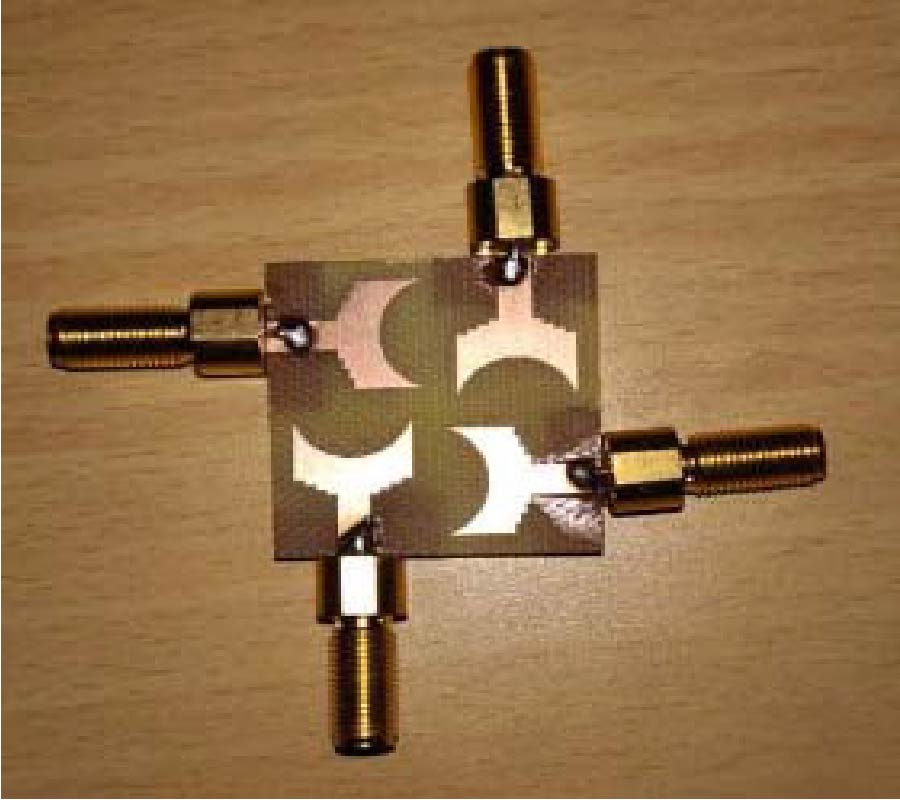
A compact 30×30 mm2 high performance four elements ultra-wide band multi-input multi-output (UWB MIMO) diversity antenna is proposed. The prototype antenna consists of four symmetrical antenna elements which are orthogonally placed on top surface of the substrate with partial slotted ground plane. The isolationamong the antenna elements is improved by placing antenna elements orthogonally without any additional decoupling structure. The various antenna characteristic parameters, i.e. return loss (< -10 dB), isolation parameter (<-22 dB), radiation patterns near omnidirectional, and maximum realized gain 4.8 dB, were measured. The MIMO performances of prototype antenna were also measured in terms of various MIMO diversity parameters and found ECC<0.06, DG>9.98 dB, TARC<-10 dB and MEG<-3 dB throughout the frequency band. This design provides an operational bandwidth from 2.15 to 16.75 GHz which covers the whole UWB spectrum and is suitable for portable devices.
COMPACT QUAD-PORT HIGH PERFORMANCE UWB MIMO/DIVERSITY ANTENNA WITH SLOTTED GROUND STRUCTURE
2021-05-10
PIER C
Vol. 112, 179-192, 2021
download: 301
An Improvised Non-Invasive Method with Clutter Removal for Dielectric Characterization of Terrestrial Rock Samples at S-Band Frequency
Anamiya Bhattacharya , Deepak Putrevu , Dharmendra Kumar Pandey and Arundhati Misra
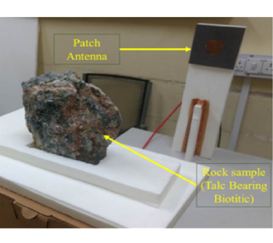
This paper presents a free-space reflection measurement technique for estimating dielectric constant and loss tangent of different materials, demonstrated for rock samples, at S-band. The method is non-contact as well as non-invasive, which is used to characterize the electromagnetic properties of different materials (in our case, rock samples) at S-band in a non-anechoic chamber environment. The technique involves measurement of reflected signals (S11 data from Vector Network Analyzer) from the material under test (MUT) as well as for the surroundings. By taking the inverse-Fourier Transform of S11 data, the impulse-response corresponding to the reflected power from the MUT can be estimated. The proposed scheme overcomes the portability issue as well as the requirement of an anechoic environment. The measurement system consists of a single antenna (centered at 2.5 GHz), rock samples (i.e. material under test (MUT)), a perfectly conducting plate and a mounting fixture. By processing and analyzing the reflection coefficient data, the values of dielectric constant and loss tangent are calculated using the proposed algorithms which take care of clutter removal as well. The technique is validated using the estimated values of rock samples corresponding to their composition values available in the literature and found to be in good agreement. Estimation of dielectric properties of rock samples will be used to validate algorithms for science studies using SAR data of Chandrayaan-2 and other planetary missions. Hence, this measurement process will play a key role towards understanding of surface composition and features of the planetary bodies.
AN IMPROVISED NON-INVASIVE METHOD WITH CLUTTER REMOVAL FOR DIELECTRIC CHARACTERIZATION OF TERRESTRIAL ROCK SAMPLES AT S-BAND FREQUENCY
2021-05-05
PIER C
Vol. 112, 165-177, 2021
download: 526
A Dual-Band, Miniaturized, AMC-Based Wearable Antenna for Health Monitoring Applications
Bo Yin , Ming Ye , Youhai Yu and Jing Gu
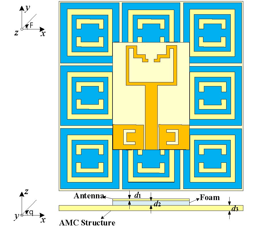
A dual-band wearable antenna operating at 2.45 GHz and 5.80 GHz with compact Artificial Magnetic Conductor (AMC) plane is proposed in this paper. The design is based on a U-shaped printed monopole antenna operating in the Industrial, Science, Medical (ISM) bands, and it is integrated with a square looped AMC plane which can reduce the overall size of the antenna system and realize miniaturization. The U-shaped monopole antenna is miniaturized by folding its arms, and its resonant frequency can be tuned easily by adjusting the length of two branches. The AMC unit, which is composed of concentric square double rings, realizes dual-band resonance. Meanwhile, a crossed patch is loaded into the inner ring to increase the electromagnetic coupling and reduce the resonance frequency of the two rings, thus miniaturizing the AMC unit. Therefore, the total size of the AMC plane which contains 3×3 elements is only 59.1 mm × 59.1 mm. Specific Absorption Rate (SAR) is examined by loading a three-layer human body tissue under the AMC antenna, and the simulation results show that SAR value is only 0.018 W/kg, which is far below the Institute of Electrical and Electronics Engineer (IEEE) standard. Finally, a prototype of the proposed antenna was fabricated and tested, and the experimental results agree well with the simulation responses.
A DUAL-BAND, MINIATURIZED, AMC-BASED WEARABLE ANTENNA FOR HEALTH MONITORING APPLICATIONS
2021-05-05
PIER C
Vol. 112, 153-164, 2021
download: 1120
Substrate Integrated Waveguide Slot Array Antenna for 77 GHz Automotive Angular Radar Applications
Xin Liao , Xing Jiang , Xue-Long Zhu , Lin Peng , Kai-Fa Wang , Ji-Heng Wang and Li-Mei Huang
A single-layer substrate integrated waveguide (SIW) longitudinal slot array antenna with low sidelobe level (SLL) in H plan and wide beamwidth in E plan is presented for 77 GHz millimeter-wave angular radar applications. The radiation energy of the antenna is determined by the length and offset of the slot. The conductance of the slot that satisfies the Taylor distribution can effectively suppress the sidelobe of antennas. Measured results indicate that the SLL of the E plane is -28.5 dB, and the 3 dB beamwidth is 98.3°. A measured peak gain of 12.7 dB is observed with a -10 dB impedance bandwidth of 75.5 GHz~77.4 GHz. The measured results are in good agreement with the theoretical calculations, and the proposed antenna has been demonstrated as a promising candidate used for millimeter-wave automotive angular radar for the proposed antenna array.
SUBSTRATE INTEGRATED WAVEGUIDE SLOT ARRAY ANTENNA FOR 77 GHZ AUTOMOTIVE ANGULAR RADAR APPLICATIONS
2021-05-04
PIER C
Vol. 112, 139-151, 2021
download: 371
Circularly Polarized Multiple Layer Dielectric Resonator Antennas
Richa Gupta , Ankit Gaur , Sandeep Gupta and Garima Bakshi
A sequence of anisotropic and isotropic materials of dielectric constant 12 and 10 respectively have been stacked alternatively to form a four-layer stack structure with aperture coupled feed mechanism for excitation. Applying this excitation, orthogonal mode pair TEδ21x and TE2δ1y has been excited at frequencies 7.54 GHz and 7.8 GHz, respectively in YZ and ZX planes to generate circular polarization. A circularly polarized bandwidth in the region (7.54 GHz-7.92 GHz) in conjunction with impedance bandwidth in the region (5.23 GHz-5.52 GHz) with a gain of 5.2 dBi has been accomplished. The designed antenna is appropriate for C-band and weather radar applications. The design assessment has been done using Ansys HFSS. The three stages of antenna design are examined. Further, the design is investigated with a 6-layer structure and an 8-layer structure.
CIRCULARLY POLARIZED MULTIPLE LAYER DIELECTRIC RESONATOR ANTENNAS
2021-05-02
PIER C
Vol. 112, 127-137, 2021
download: 529
Wide-Band Log-Periodic Microstrip Antenna with Defected Ground Structure for C-Band Applications
Kunal Krishna Upadhyay , Alkesh Agrawal and Mukul Misra
The manuscript presents a log-periodic microstrip antenna with a defective ground structure (LPMADGS). The antenna is simulated, designed, and validated for C-band applications. The design of the antenna consists of three layers with upper most layer consisting of log-periodic, copper patches with a thickness of 0.035 mm; the middle layer is a 2 mm thick dielectric layer of FR-4 substrate; and the bottom layer is a defected ground structure (concentric ring resonators of 0.035 mm thickness). The suggested antenna design is simulated with a complete ground plane, without ground plane, and with a defective ground plane. The proposed antenna with optimized design is fabricated by wet etched method. The simulated results are approximately similar to the experimentally measured results. The experimentally measured results show transmission peaks at 7.65 GHz and 7.90 GHz. The resonating effect of log-periodic patches with a defected ground structure results in wide-band of 0.91 GHz (-10 dB bandwidth). The proposed antenna structure exhibits a wide bandwidth transmission which mostly resonates in frequency range that lies in C-band. It has future applications for mobile as well as wireless communication.
WIDE-BAND LOG-PERIODIC MICROSTRIP ANTENNA WITH DEFECTED GROUND STRUCTURE FOR C-BAND APPLICATIONS
2021-04-30
PIER C
Vol. 112, 113-125, 2021
download: 441
Enhanced Ultra-Wide Band Multistage Rectifier for Pulsed Signal Power Transmission
Ahmed Moulay and Tarek Djerafi
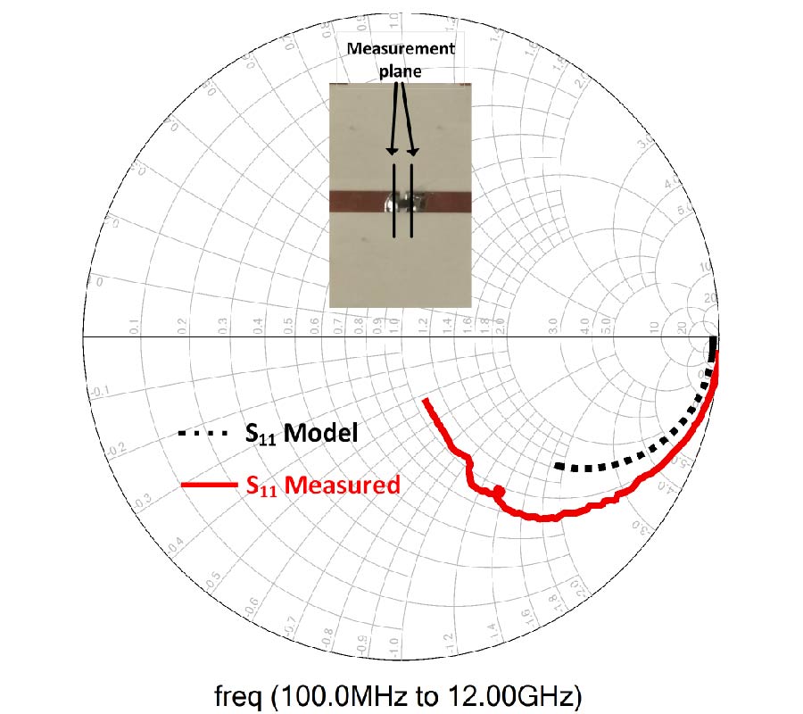
This paper presents a multi-sections broad-band radio-frequency (RF) to direct-current (dc) power rectifier for pulsed signal transfer. The power transfer using a pulse allows to use a signal with low power spectral density. The optimal distributed configuration with critical parameters is studied to enhance the efficiency over broadband frequency and wide power range. A five stage distributed RF-dc converter arrangement with micro-strip transmission line ensures the power harvesting from 100 MHz to 11 GHz. The designed and fabricated circuit is characterized at multi-frequencies of ultra-wide band (UWB). The distributed harvester significantly improves the detected voltage over a wide bandwidth compared to conventional RF detectors. The achieved efficiency with optimized parameters is 48% with five-stage harvester. A maximum dc output of 956 mV is reached at 8 dBm of input power of sinusoidal single tone signal at 1 GHz of frequency. The designed prototype is associated with a square wave signal to show the circuit potential in terms of power transfer. The output voltage can be controlled with input signal level, frequency as well as the pulse width. For the power transfer circuit, 996 mV of maximum dc output voltage is reached for 1 V of input amplitude at 1 GHz with duty cycle of 50%. The efficiency increases significantly with duty cycle ratio of the input signal. The power harvester associated with a UWB antenna confirms the benefit of using a square wave signal in the case of power harvesting or transfer.
ENHANCED ULTRA-WIDE BAND MULTISTAGE RECTIFIER FOR PULSED SIGNAL POWER TRANSMISSION
2021-04-26
PIER C
Vol. 112, 99-111, 2021
download: 547
Stubs and Slits Loaded Partial Ground Plane Inspired Novel Hexagonal Ring-Shaped Fractal Antenna for 5G/LTE/RFID/GSM/Bluetooth/WLAN/WiMAX Wireless Applications: Design and Measurement
Narinder Sharma and Sumeet Singh Bhatia
A multiband hexagonal ring-shaped fractal antenna with stubs and slits loaded partial ground plane has been presented in this manuscript. The proposed antenna is compact in size 24×30×1.6 mm3 and exhibits enhanced bandwidth, gain, and reflection coefficient. Measured results exhibit that the proposed antenna resonates with impedance bandwidth (S11 ≤ -10 dB) in the frequency ranges 1.0-2.75 GHz, 4.74-8.70 GHz, 11.04-12.76 GHz, 14.97-16.62 GHz, and 19.70-22.0 GHz. These frequency ranges cover distinct wireless standards such as 1800 MHz 2G spectrum of GSM band (1.71-1.88 GHz), LTE 2300/LTE 2500 (2.3-2.4 GHz/2.5-2.69 GHz), RFID/Bluetooth (2.4 GHz), 5G spectrum band (5900-6400 MHz) adopted by European Union, Long Term Evolution (LTE) band 46 (5150-5925 GHz), RFID (5.4 GHz), WLAN (5.15-5.35 and 5.72-5.85 GHz), Wi-MAX (5.25-5.85 GHz), FSS (11.45-11.7/12.5-12.75 GHz), defence systems (14.62-15.23 GHz), aeronautical radio navigations (15.43-17.3 GHz), and fixed/mobile satellite communications (19.7-20.1 GHz and 20.2- 21.2 GHz). The proposed antenna reveals the positive value of peak realized gain with almost omnidirectional radiation patterns in E- and H-planes for all the resonant frequency bands. The performance of proposed antenna has been realized by using HFSS V13 simulator based on FEM (Finite Element Method), and the results are compared with the experimental results which are in good agreement with each other.
STUBS AND SLITS LOADED PARTIAL GROUND PLANE INSPIRED NOVEL HEXAGONAL RING-SHAPED FRACTAL ANTENNA FOR 5G/LTE/RFID/GSM/BLUETOOTH/WLAN/WIMAX WIRELESS APPLICATIONS: DESIGN AND MEASUREMENT
2021-04-25
PIER C
Vol. 112, 83-98, 2021
download: 550
Inset-Fed Planar Antenna Array for Dual-Band 5G MIMO Applications
Umair Rafique , Shobit Agarwal , Nasir Nauman , Hisham Khalil and Khalil Ullah
An inset-fed planar MIMO antenna array design has been presented for dual-band 5G applications. The proposed MIMO array offers numerous advantages such as compact size, planar structure, and high isolation. The single element of the array comprises an inset-fed rectangular patch and open circuit stubs designed on the top side of the substrate, while the bottom layer consists of a partial ground plane. Simulated and measured results show that the proposed antenna offers dual-band characteristics at 28 GHz and 38 GHz frequency bands, respectively. It has also been observed from the results that the proposed inset-fed planar antenna offers good radiation characteristics, and acceptable gain and radiation efficiency. Furthermore, four-elements based MIMO antenna array has been designed for its possible use in 5G enabled communication devices. It has been demonstrated that the proposed MIMO antenna provides high isolation between array elements without disturbing the return loss of an individual element. The proposed MIMO antenna array has been fab- ricated and measured for the validation of simulation results, and it has been observed that both the results are in good agreement.
INSET-FED PLANAR ANTENNA ARRAY FOR DUAL-BAND 5G MIMO APPLICATIONS
2021-04-22
PIER C
Vol. 112, 69-82, 2021
download: 583
Research on Conducted EMI Characteristics of SiC MOSFET Considering Temperature Effect
Ming-Xing Du , Weiguo Bian , Hongbin Wang , Qiqi Dai and Ziwei Ouyang
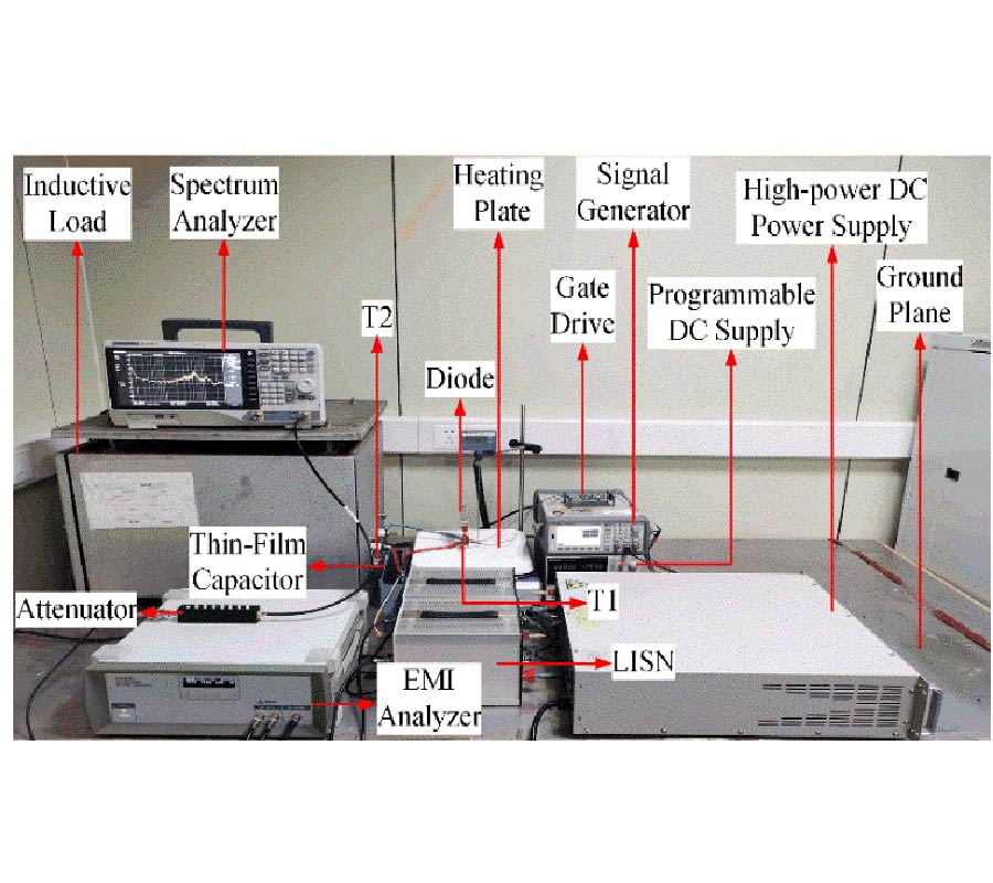
The junction temperature change of SiC MOSFET will change its switching process, and then affect the electromagnetic interference (EMI) characteristics of the system where the device is located and the safe operation of the surrounding equipment. Therefore, it is of great significance to research the temperature dependence of its EMI characteristics. In this paper, a buck converter composed of SiC MOSFET is taken as the research object to study the temperature variation characteristics of the conducted EMI spectrum during the switching process. Combined with the specific circuit connection form of the buck converter, the coupling paths of the conducted EMI are determined, and then the influence mechanisms of temperature change on the differential mode (DM) interference and common mode (CM) interference are analyzed. The theoretical analysis and experimental results show that the DM interference of the buck converter composed of SiC MOSFET increases with the increase of temperature, and the CM interference is almost unaffected by temperature. When the working temperature increases from 25˚C to 145˚C, the peak value of DM voltage increases by 6.7 dBμV, and the peak value of CM voltage changes less than 1.4 dBμV.
RESEARCH ON CONDUCTED EMI CHARACTERISTICS OF SIC MOSFET CONSIDERING TEMPERATURE EFFECT
2021-04-20
PIER C
Vol. 112, 55-68, 2021
download: 542
Design and Performance Analysis of g -Shaped Compact ACS Fed 4-Port MIMO Antenna for Triple Frequency Band Applications
Praveen Naidu , Akkapanthula Saiharanadh , Dhanekula Maheshbabu , Arvind Kumar and Neelima Dudi
In this paper, a novel compact single element G-shaped Asymmetric Coplanar Strip (ACS) fed antenna and its four-element printed multiple-input multiple-output (MIMO) antenna have been presented with multi-band frequency characteristics. The proposed MIMO antenna has been fabricated on an FR-4 substrate (46 × 46 × 1.6) mm3 with dielectric constant εr = 4.4. The desired isolation between the elements (-18 dB) is achieved by placing the antenna elements orthogonal to each other. Simulated and measured results show that return loss (S11) for the proposed MIMO antenna is less than -10 dB in the operating bands, with frequency ranging 2.30-2.45 GHz, 3.36-3.65 GHz, and 4.53-5.88 GHz, respectively, which ensures its operation in multiple frequency bands. Moreover, these bands are obtained for 2.3 GHz WiBro, LTE and 5G NR to cover B40/B42/N30/N40/N97 together with 3.5 GHz/5 GHz WiMAX/WLAN band applications. Meanwhile, the diversity performance characteristics like ECC (Envelope Correlation Coefficient), MEG (Mean Effective Gain), DG (Diversity Gain), Total Active Reflection Coefficient (TARC), and Channel Capacity Loss (CCL) have been calculated and are presented in this paper. The correlation coefficient is found to be less than 0.001 with a diversity gain greater than 9.95, and an acceptable channel capacity loss is less than 0.4 bits/s/Hz.
DESIGN AND PERFORMANCE ANALYSIS OF G-SHAPED COMPACT ACS FED 4-PORT MIMO ANTENNA FOR TRIPLE FREQUENCY BAND APPLICATIONS
2021-04-19
PIER C
Vol. 112, 45-54, 2021
download: 346
An Analysis of High Selectivity and Harmonic Suppression Based on Stepped-Impedance Resonator Structure for Dual-Mode Diplexer
Jessada Konpang and Natchayathorn Wattikornsirikul
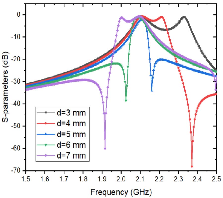
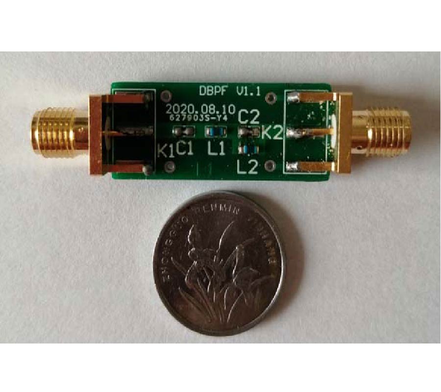
A high selectivity microstrip dual-mode diplexer with a stepped-impedance opened-end structure is implemented to reduce the size of a dual-mode resonator and suppress the harmonics. The proposed dual-mode resonator structure consists of a microstrip half-wavelength resonator and an open-circuited stepped-impedance stub. The stepped-impedance opened-end structure can control an even mode in the upper and lower desired bands to improve the cutoff responses. The sharp cutoff selectivity of the filter is created to improve the diplexer performance and wide suppress harmonics. The dual-mode diplexer prototype is analyzed, fabricated, and measured. The measured result agrees well with the analyzed result. The simulated and measured dual-mode diplexers are designed at the operational frequency of Tx/Rx at 1.95 GHz and 2.14 GHz, respectively. It is shown that the dual-mode filter has a wide stopband, including the first spurious resonance frequency due to the stepped-impedance stub.
AN ANALYSIS OF HIGH SELECTIVITY AND HARMONIC SUPPRESSION BASED ON STEPPED-IMPEDANCE RESONATOR STRUCTURE FOR DUAL-MODE DIPLEXER
2021-04-16
PIER C
Vol. 112, 35-44, 2021
download: 360
A New Reflectionless Filter Composed of Discharging Circuit
Aixia Yuan , Shao-Jun Fang , Ying Wang , Yu Lin Feng and Tielin Zhang
A new reflectionless filter with discharging circuit is presented. Under the premise of keeping the original filter unchanged, a discharging circuit is added. The relationship between the passband and stopband of the discharging circuit and the original filter is similar to the duality of the circuit. Without affecting the performance of the original filter, the reflected energy of the original filter is discharged to the ground through discharging circuit, so as to achieve no reflection of the filter, avoiding the interference to the input. Analytical design equations are provided so that the reflectionless filter can be designed. According to this design method, the reflectionless dual-band bandpass filter is designed and fabricated. Simulation and measurement results are in agreement. It has good reflectionless performance. The feasibility of the design method is verified.
A NEW REFLECTIONLESS FILTER COMPOSED OF DISCHARGING CIRCUIT
2021-04-13
PIER C
Vol. 112, 21-34, 2021
download: 329
Simultaneous Measurement of Temperature and Strain Using Multi-Core Fiber Within-Line Cascaded Symmetrical Ellipsoidal Fiber Balls-Based Mach-Zehnder Interferometer Structure
Farhan Mumtaz , Hongfeng Lin , Yutang Dai , Wenbin Hu , Muhammad Aqueel Ashraf , Lashari Ghulam Abbas , Shu Cheng and Pu Cheng
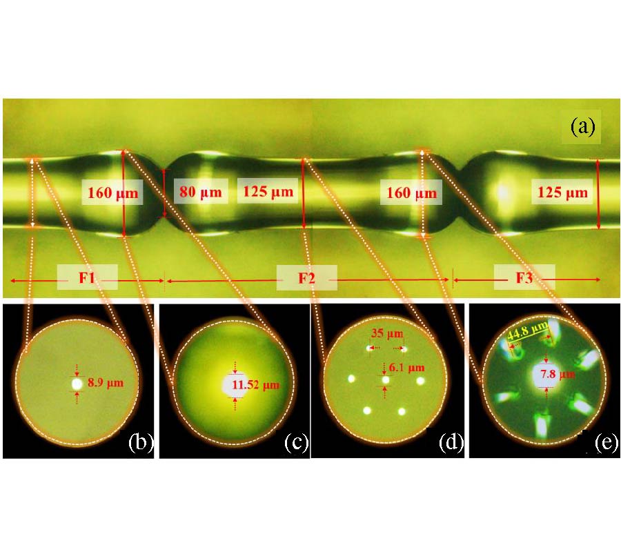
Simultaneous measurement of temperature and strain using multi-core fiber (MCF) with an in-line cascaded symmetrical ellipsoidal fiber balls structure of Mach-Zehnder interferometer (MZI) is presented. The sensor is fabricated by using an ordinary fusion apparatus. The thermo-coupling effect is realized through Germanium (Ge)-doped central and hexagonal distributed outer cores of MCF. A high-quality transmission spectrum is obtained with a fringe visibility of 12-15 dB and higher extinction ratio. The sensor exhibits superior mechanical strength compared with the fragile structures, such as tapered, etched, misaligned and offset fibers. The temperature sensitivity of 137.6 pm/°C and 68.1 pm/°C in the range of 20-90°C, and the strain sensitivity of -0.42 pm/με and -1.19 pm/με in the range of 0-801 με are obtained, when probe ``L'' is 40 mm and 20 mm, respectively. Simultaneous measurement of temperature and strain can be achieved by solving the coefficient matrix and tracing the wavelength shifts in the interference spectrum. Besides, the sensor has many advantages, such as high sensitivity, easy fabrication, simple structure, being stable and inexpensive, which may find potential applications in the field of optical sensing.
SIMULTANEOUS MEASUREMENT OF TEMPERATURE AND STRAIN USING MULTI-CORE FIBER WITHIN-LINE CASCADED SYMMETRICAL ELLIPSOIDAL FIBER BALLS-BASED MACH-ZEHNDER INTERFEROMETER STRUCTURE
2021-04-11
PIER C
Vol. 112, 11-20, 2021
download: 338
Dual-Band Subharmonic Mixer for WiFi Application with Improved Conversion Loss and RF-to-IF Isolation
Kumari Pushpa and Jayanta Ghosh
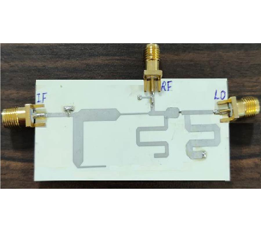
A dual-band subharmonic mixer that employs both the second and fourth harmonics of a local oscillator signal in the mixing process is demonstrated for WIFI application. The design results in a simple and cost-effective mixer as it requires only one local oscillator (LO). A quarter-wave stepped impedance stub has been used to suppress both bands of radio frequency (RF) signal. The proposed dual-band subharmonic mixer is designed for two RF bands with the center frequencies at 2.45 GHz and 5 GHz using a single LO frequency at 1.3 GHz. For mixing purpose, the second and fourth harmonics of LO are utilized. Experimental measurements show high port-to-port isolation and achieve minimum conversion losses of 6.87 dB and 10.0 dB at 2.59 GHz and 5 GHz, respectively. The 3-dB RF bandwidth is 2.3 to 2.95 GHz for the second harmonic and 4.8 to 5.5 GHz for the fourth harmonic of LO signal. The input P1-dB compression points for two modes of the mixer are -9 dBm and -5 dBm, respectively. The RF-to-IF isolations are more than 18 dB (maximum 36 dB) and 20 dB (maximum 33 dB), over both the RF bands.
DUAL-BAND SUBHARMONIC MIXER FOR WIFI APPLICATION WITH IMPROVED CONVERSION LOSS AND RF-TO-IF ISOLATION
2021-04-22
PIER C
Vol. 112, 1-10, 2021
download: 299
DOA Estimation of Mixture Signals Based on the PSA
Wen Dong , Qianrong Lu , Siyuan Wu , Shujie Lei and Bin Pu
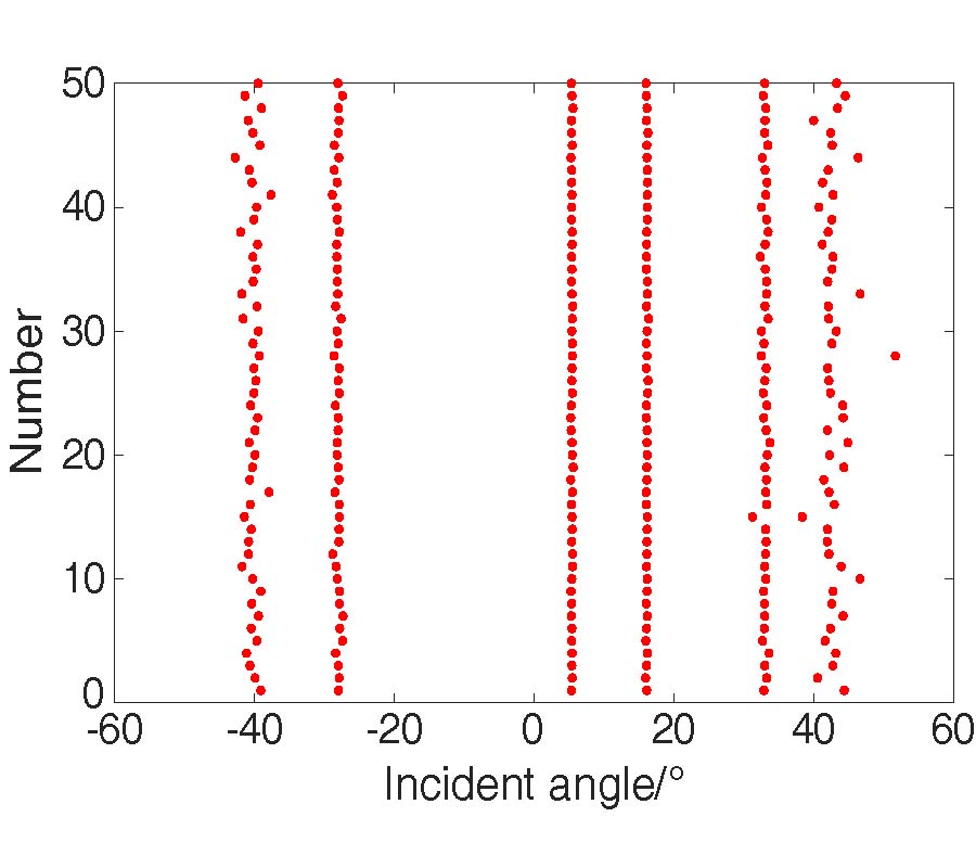
The problem of direction of arrival (DOA) estimation based on a polarization sensitive array (PSA) is considered in this paper. In the environment of the mixture signal, a novel DOA estimation for both the independent signals and the coherent signals is proposed. The process of estimation is divided into two steps. First, the root-multiple signal classification algorithm is employed to estimate the DOAs of the independent signals. Then, the data covariance matrix which only contains the information of the coherent signals is estimated with improved vector reconstruction technique. Theoretical analysis and simulation results show that the proposed method can expand the array aperture and has small computation load as well as excellent estimation performance.
DOA ESTIMATION OF MIXTURE SIGNALS BASED ON THE PSA