Vol. 125
Latest Volume
All Volumes
PIERM 130 [2024] PIERM 129 [2024] PIERM 128 [2024] PIERM 127 [2024] PIERM 126 [2024] PIERM 125 [2024] PIERM 124 [2024] PIERM 123 [2024] PIERM 122 [2023] PIERM 121 [2023] PIERM 120 [2023] PIERM 119 [2023] PIERM 118 [2023] PIERM 117 [2023] PIERM 116 [2023] PIERM 115 [2023] PIERM 114 [2022] PIERM 113 [2022] PIERM 112 [2022] PIERM 111 [2022] PIERM 110 [2022] PIERM 109 [2022] PIERM 108 [2022] PIERM 107 [2022] PIERM 106 [2021] PIERM 105 [2021] PIERM 104 [2021] PIERM 103 [2021] PIERM 102 [2021] PIERM 101 [2021] PIERM 100 [2021] PIERM 99 [2021] PIERM 98 [2020] PIERM 97 [2020] PIERM 96 [2020] PIERM 95 [2020] PIERM 94 [2020] PIERM 93 [2020] PIERM 92 [2020] PIERM 91 [2020] PIERM 90 [2020] PIERM 89 [2020] PIERM 88 [2020] PIERM 87 [2019] PIERM 86 [2019] PIERM 85 [2019] PIERM 84 [2019] PIERM 83 [2019] PIERM 82 [2019] PIERM 81 [2019] PIERM 80 [2019] PIERM 79 [2019] PIERM 78 [2019] PIERM 77 [2019] PIERM 76 [2018] PIERM 75 [2018] PIERM 74 [2018] PIERM 73 [2018] PIERM 72 [2018] PIERM 71 [2018] PIERM 70 [2018] PIERM 69 [2018] PIERM 68 [2018] PIERM 67 [2018] PIERM 66 [2018] PIERM 65 [2018] PIERM 64 [2018] PIERM 63 [2018] PIERM 62 [2017] PIERM 61 [2017] PIERM 60 [2017] PIERM 59 [2017] PIERM 58 [2017] PIERM 57 [2017] PIERM 56 [2017] PIERM 55 [2017] PIERM 54 [2017] PIERM 53 [2017] PIERM 52 [2016] PIERM 51 [2016] PIERM 50 [2016] PIERM 49 [2016] PIERM 48 [2016] PIERM 47 [2016] PIERM 46 [2016] PIERM 45 [2016] PIERM 44 [2015] PIERM 43 [2015] PIERM 42 [2015] PIERM 41 [2015] PIERM 40 [2014] PIERM 39 [2014] PIERM 38 [2014] PIERM 37 [2014] PIERM 36 [2014] PIERM 35 [2014] PIERM 34 [2014] PIERM 33 [2013] PIERM 32 [2013] PIERM 31 [2013] PIERM 30 [2013] PIERM 29 [2013] PIERM 28 [2013] PIERM 27 [2012] PIERM 26 [2012] PIERM 25 [2012] PIERM 24 [2012] PIERM 23 [2012] PIERM 22 [2012] PIERM 21 [2011] PIERM 20 [2011] PIERM 19 [2011] PIERM 18 [2011] PIERM 17 [2011] PIERM 16 [2011] PIERM 14 [2010] PIERM 13 [2010] PIERM 12 [2010] PIERM 11 [2010] PIERM 10 [2009] PIERM 9 [2009] PIERM 8 [2009] PIERM 7 [2009] PIERM 6 [2009] PIERM 5 [2008] PIERM 4 [2008] PIERM 3 [2008] PIERM 2 [2008] PIERM 1 [2008]
2024-03-25
PIER M
Vol. 125, 143-151, 2024
download: 141
A New Robust Adaptive Beamforming Algorithm Based on GSC
Xiaohan Guan , Yao Chen and Encheng Wang
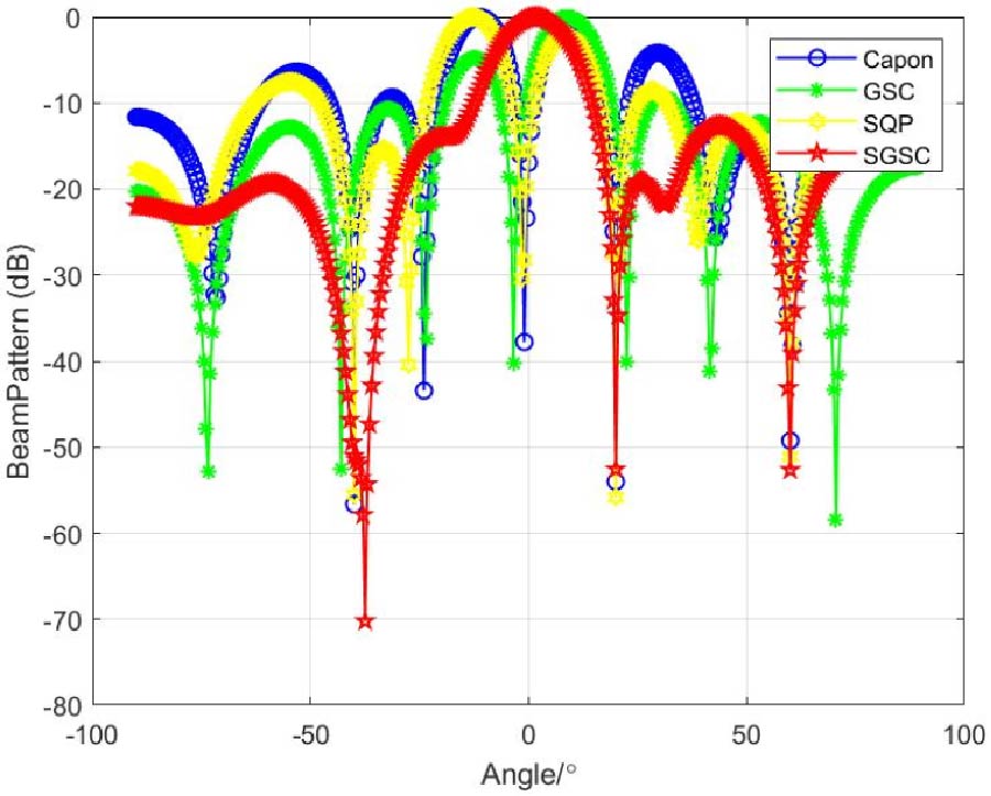
The generalized sidelobe cancellation (GSC) is a commonly used adaptive beamforming technology, which can be used in antenna arrays. Due to the error of the direction of arrival of the received signal and the spacing error of the received array elements, the signal received by the array antenna has a mismatch of steering vectors, which leads to that the GSC method cannot accurately aim at the expected signal and suppress the interference signal. In order to improve the robustness of GSC algorithm, a new adaptive beamforming algorithm named SGSC (Sequential Quadratic Programming-Generalized Side Lobe Cancellation) is proposed in this paper. In this method, firstly, the mismatching expected signal steering vector is corrected by the stepwise quadratic programming, so that the auxiliary antenna can effectively block the expected signal. Then, the optimal weight vector is obtained by combining the corrected steering vector with the GSC, so that the expected signal components of the auxiliary antenna and of the main antenna can be avoided from being cancelled due to mismatch errors. Finally, the simulation results based on MATLAB show that the new algorithm can point the desired signal more accurately and suppress the interference signal more obviously in the presence of mismatch error, which shows the effectiveness of the method.
A New Robust Adaptive Beamforming Algorithm Based on GSC
2024-03-22
PIER M
Vol. 125, 135-142, 2024
download: 334
A Compact High Gain Circular Shaped Two-Port MIMO Antenna with Fractal DGS for Downlink Satellite Communication
Manjula Sanugomula and Ketavath Kumarnaik
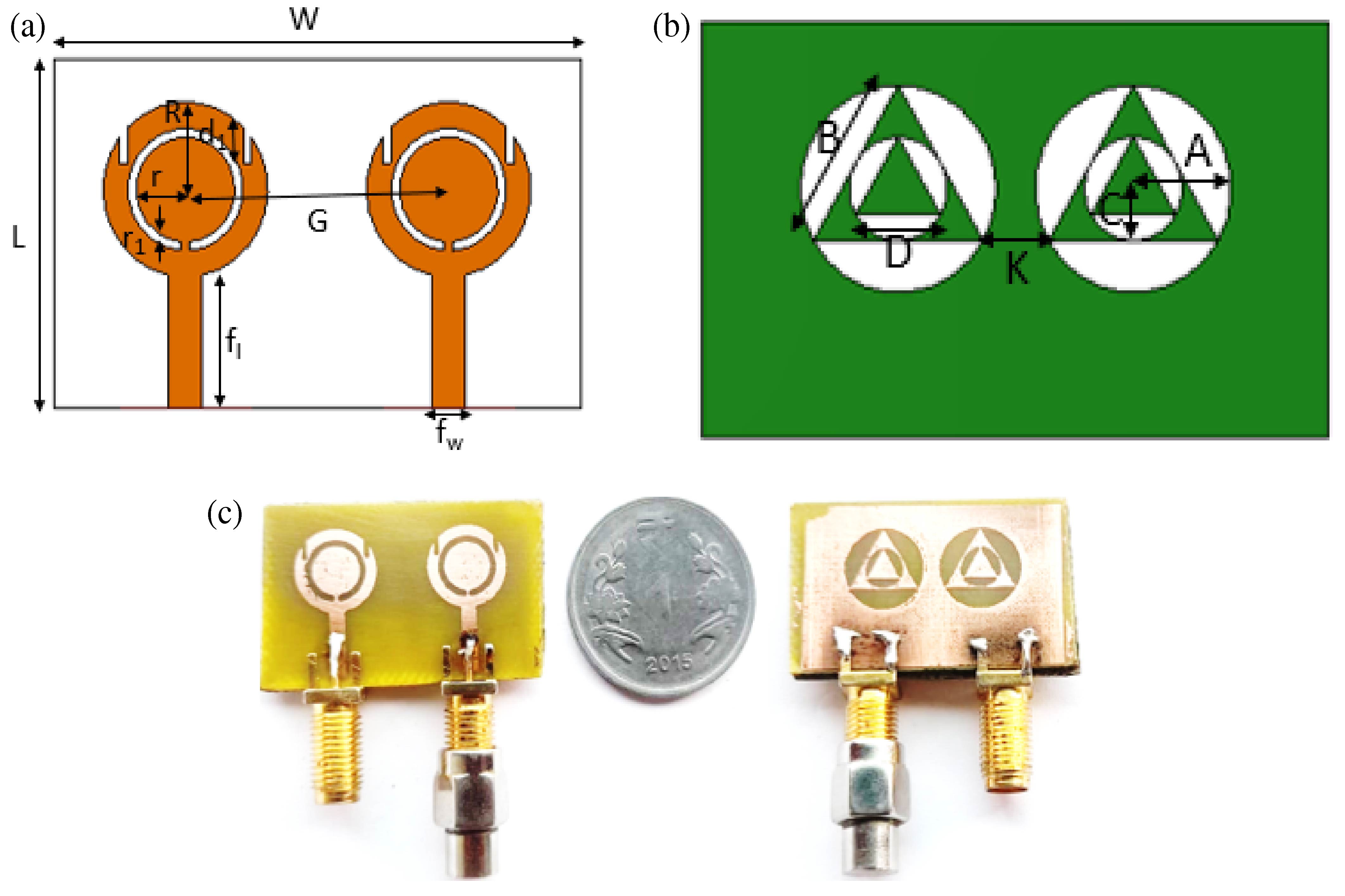
This paper presents an innovative high gain multiple-input-multiple-output antenna featuring a compact circular shape, enhanced by strategically positioned slots, slits, and defected grounds created by etching multiple iterations of circle inserted with triangle shape. The investigation thoroughly explores the various traits and properties exhibited by the antenna. The antenna design harmoniously incorporates two radiating elements shaped in circles, positioned 16 mm apart from their centers, and has been physically constructed using an FR4 substrate. Enhancing the antenna's bandwidth and gain requires the implementation of slots with fractal patterns on the ground with a precise edge-to-edge separation of 2.5 mm. The placement of the antenna elements at a 16 mm distance guarantees an isolation level exceeding 15 dB consistently throughout the entire wideband frequency range. The dimensions of the compact MIMO antenna are tailored to be 1.12λ × 1.8λ × 0.091λ (20 × 32 × 1.62 mm3). In this study, the circular patch MIMO antenna with a fractal DGS resonates precisely at 16.903 GHz. It showcases an impressive impedance bandwidth spanning 2.027 GHz, ranging from 15.946 GHz to 17.973 GHz. It exhibits a reflection coefficient of -43.82 dB and achieves an observed gain of 6.25 dBi. The observed results include a minimal envelope correlation coefficient (<0.025) and a substantial Diversity Gain (>9.89). The measured results mirror the simulated outcomes, affirming the effectiveness of the wideband, high-gain antenna design. Its bandwidth and gain are well-suited for Satellite Communications particularly in downlink applications, enabling faster data transmission rates.
A Compact High Gain Circular Shaped Two-port MIMO Antenna with Fractal DGS for Downlink Satellite Communication
2024-03-22
PIER M
Vol. 125, 127-134, 2024
download: 184
An Optimization of Subarrayed Planar Array Pattern via Fractal Structure Thinning
Ahmed Jameel Abdulqader
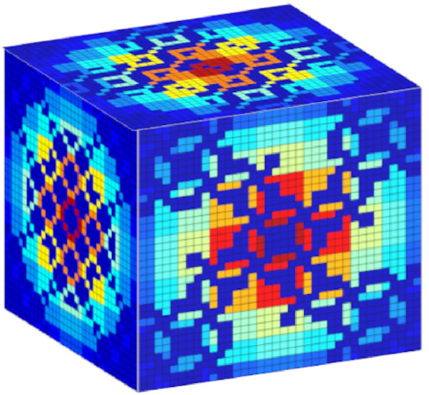
Dividing large planar arrays into several subarrays and then turning off some of them reduces the complexity (cost) of the system significantly. In this paper, two optimization stages for the formation of planar subarrays and the removal of some of them are proposed. The first optimization stage improves the pattern of the original planar array after dividing it into a set of rotational square and rectangular subarrays. In the second optimization stage, it works to remove some of the subarrays completely or partially, depending on new fractal structures derived from the conventional Sierpinski carpet structure. The proposed fractal-thinned planar array is based on amplitude-only excitation, i.e. the phases of the elements are set to zero. To execute the optimization steps above, a genetic algorithm (GA) is used. Some determinants are included in the optimization process to maintain the properties of the desired pattern. Simulation results showed the effectiveness of the proposed optimization method in achieving almost the same performance in both stages of optimization.
An Optimization of Subarrayed Planar Array Pattern via Fractal Structure Thinning
2024-03-22
PIER M
Vol. 125, 117-125, 2024
download: 156
Noncontact Voltage Measurement System for Low-Voltage Power Line
Huafeng Su , Haojun Li , Weihao Liang , Chaolan Shen and Zheng Xu
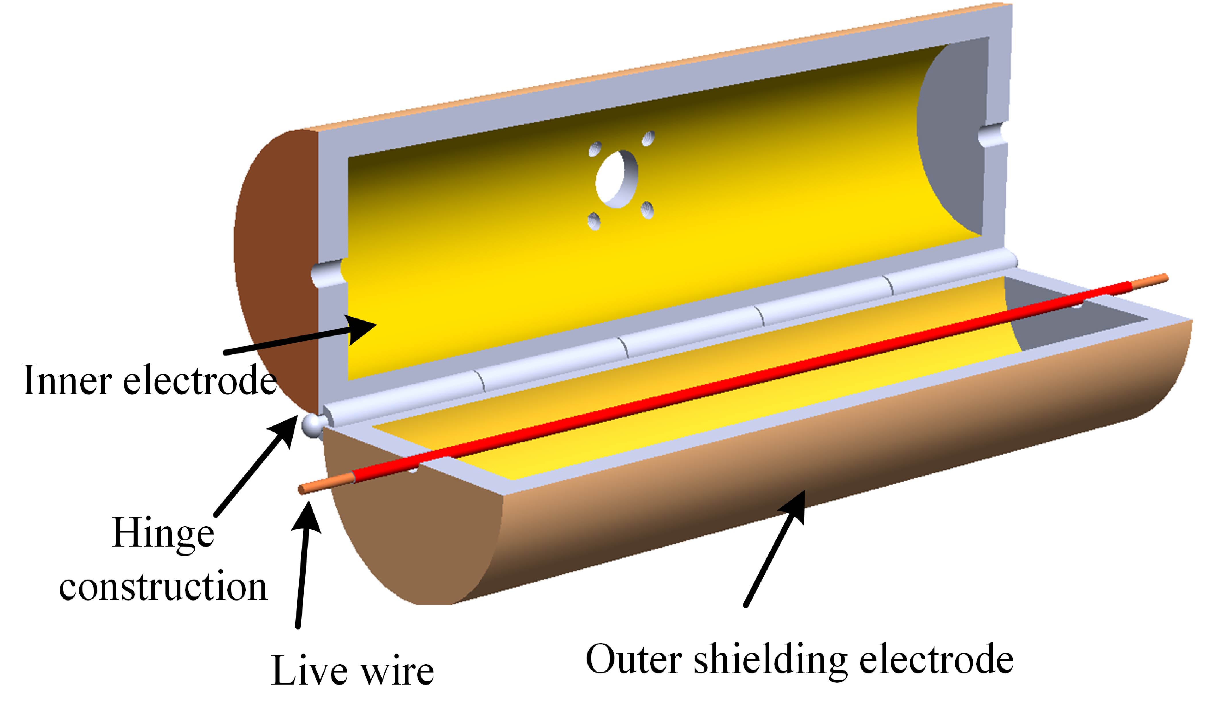
As one of the most basic electric quantities in the power system, voltage plays an important role in many fields such as condition monitoring and fault diagnosis. The construction and development of the smart grid cannot be separated from the reform and progress of the advanced sensing and measurement technology. Noncontact voltage measurement technology, as one of the important technologies, has many advantages such as no electrical contact, low insulation requirements, easy installation, and great potential in improving the panoramic perception ability of the power system. In this paper, a noncontact measurement method of the power line voltage based on capacitive coupling principle is proposed, which realizes the reliable measurement of the line voltage waveform. First, the principle of the noncontact voltage measurement method is introduced, which mainly includes self-calibration and online measurement of the sensor. The high-frequency voltage signal is injected into the capacitive coupling network of the sensor to implement the self-calibration of the sensor. Then, the digital integration method is used to integrate the output signal of the sensor to measure the line voltage waveform. Second, the noncontact voltage sensor prototype and the signal processing circuit are designed. Finally, the test platform of the line voltage measurement is built, and the measurement test of 220 V/50 Hz line voltage waveform is carried out. The test results show the relative amplitude error of the voltage measured by the sensor is less than 2.5%, the maximum phase error less than 2° at 50 Hz, and the linearity better than 0.5%. The frequency response experiment shows that the system has almost constant gain in the frequency range of 50-1800 Hz, and the phase error reaches a maximum of 2.8° at a frequency of 1800 Hz.
Noncontact Voltage Measurement System for Low-voltage Power Line
2024-03-18
PIER M
Vol. 125, 107-116, 2024
download: 283
Design of a Monopole Antenna for WiFi -UWB Based on Characteristic Mode Theory
Zhonggen Wang , Rui You , Ming Yang , Jinzhi Zhou and Mingqing Wang
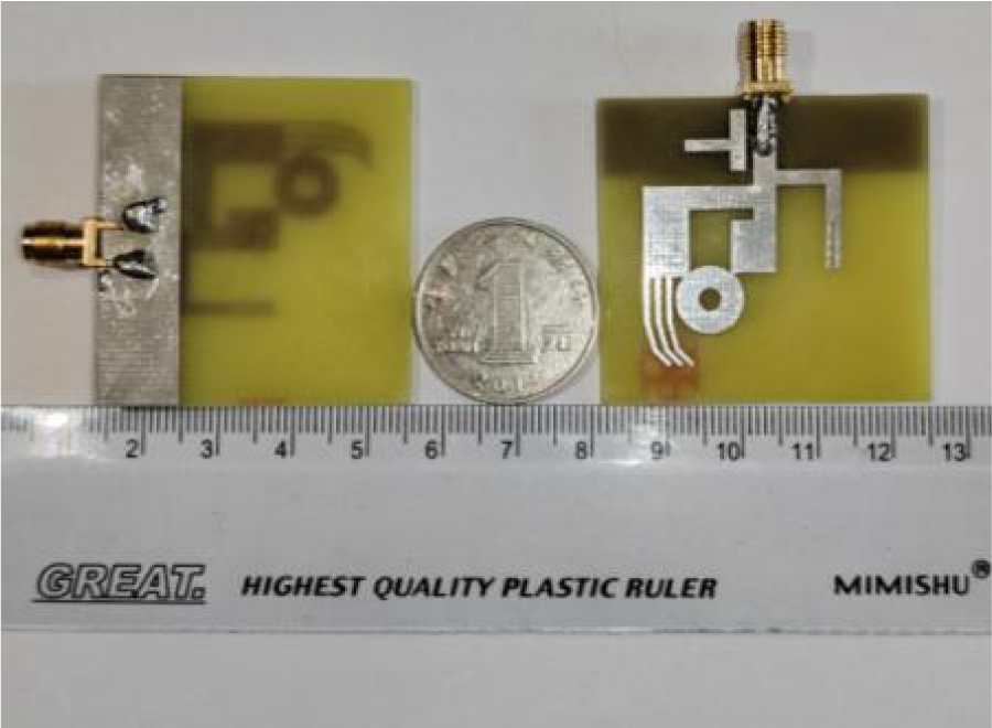
In this paper, a WiFi-UWB multiband monopole antenna is designed, fabricated, and tested based on the characteristic mode theory, which mainly consists of an L-shaped metal, an ``ok''-shaped metal radiator, and a T-shaped metal patch. The substrate dimensions are 40×43×1.6 mm3, featuring a rectangular ground plate at the substrate's bottom. The ``ok''-shaped metal on the upper surface is composed of a metal ring and a curved finger-shaped metal. To improve impedance matching and broaden the bandwidth, strategic modifications are implemented. Specifically, a rectangular slot is introduced at the top of the L-shaped metal, and the T-shaped metal is rotated 90° counterclockwise and positioned beneath the ``ok''-shaped metal. The microstrip feed line, constructed from metal, incorporates a feed point. Simulation results indicate that the antenna effectively covers the frequency ranges of 2.30-2.50 GHz and 3.65-9.77 GHz. At the resonance point, the maximum return loss is below -40 dB, signifying superior directional radiation characteristics. The antenna design is characterized by a wide frequency band, simple structure, and holds significant practical value for multi-frequency communication.
Design of a Monopole Antenna for WiFi-UWB Based on Characteristic Mode Theory
2024-03-17
PIER M
Vol. 125, 97-105, 2024
download: 288
Stack Dual-Band EBG Based Sensor for Dielectric Characterization of Liquids
Pramod P. Bhavarthe , Alam N. Shaikh and Kompella S. L. Parvathi
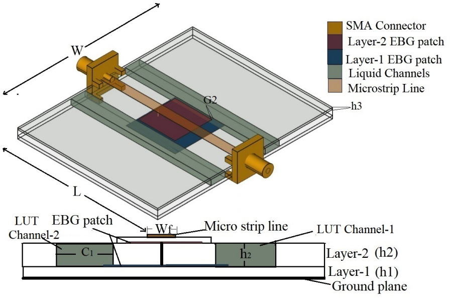
A tiny electromagnetic band gap (EBG) based microwave sensor with dual-band operation for dielectric characterization of Liquids is presented in this work. The suggested design uses a suspended microstrip line placed over the stack dual-band type EBG (SD-EBG) unit cell at 2.40 GHz and 2.98 GHz. To achieve the dual band characteristics, the stack type of EBG with different patch sizes and offset vias is used. To validate the sensor performance, absolute solution of butan-l-o1, methonal, and water are considered as liquid under test (LUT) and loaded in transparent polypropylene (PP) material, and the maximum sensitivity of 1.14% from the first resonance with maximum Q-factor of 137.5 from the second resonance is achieved with frequency detection resolution of 27.4 MHz. The size of proposed SD-EBG based sensor is 54.95% and 39.02% of that of planar EBG based sensor and cesaro fractals EBG based sensor.
Stack Dual-band EBG Based Sensor for Dielectric Characterization of Liquids
2024-03-16
PIER M
Vol. 125, 87-95, 2024
download: 243
Multi-Band Notched Circular Polarized MIMO Antenna for Ultra-Wideband Applications
Ekta Thakur , Naveen Jaglan , Anupma Gupta and Ahmed Jamal Abdullah Al-Gburi
The paper details the development of an innovative Ultra-Wideband (UWB) Circularly Polarized (CP) Multi-Input Multi-Output (MIMO) antenna. Drawing inspiration from an Electromagnetic Band-Gap Structure, the antenna incorporates two compact electromagnetic bandgap cells strategically positioned near the feedline. The result is a sophisticated triple-band notched planar antenna configuration. To enhance its performance, a slot and a stub are strategically added to the ground plane, effectively broadening the Axial Ratio Bandwidth (ARBW). This carefully designed setup achieves a wide ARBW while simultaneously rejecting interference at 3.5, 5.5, and 8.2 GHz. Notably, the MIMO antenna demonstrates an axial ratio spanning from 3 to 10.4 GHz, coupled with an impedance bandwidth ranging from 3.1 to 10.6 GHz. Diversity features of the proposed structure are quantified through three key parameters: ECC (Envelope Correlation Coefficient) greater than 0, TARC (Total Active Reflection Coefficient) surpassing 10, and DG (Diversity Gain) exceeding 9.7. These parameters collectively indicate robust diversity characteristics, underscoring the antenna's efficacy in challenging communication scenarios. Practical implementation involves the use of FR4 dielectric substrates, with precise measurements of 42.7×55×1.6 mm3. This meticulous construction ensures the realization of the proposed structure's theoretical framework, highlighting the antenna's potential applicability in advanced UWB communication systems.
Multi-band Notched Circular Polarized MIMO Antenna for Ultra-wideband Applications
2024-03-15
PIER M
Vol. 125, 75-85, 2024
download: 254
A SM-PB Acceleration Algorithm for Calculating Electromagnetic Scattering from 2D Gaussian Rough Surfaces
Shaoliang Yuan
In this paper, an SM-PB (Sparse Matrix Canonical Grid method-Physics Based Two Grid) acceleration algorithm is proposed which can be used to calculate electromagnetic scattering from two-dimensional rough surfaces with large dielectric constants. Firstly, a two-dimensional rough surface model is established based on the Monte Carlo method and Gaussian spectral function, and a conical incident wave with Gaussian characteristics is introduced to eliminate the error caused by artificial truncation of the rough surface. In the scattering calculation, the integral equation of the rough surface is processed by the SMCG algorithm, and then the matrix equation is further processed by applying the PBTG algorithm to decompose the matrix equation into the very near-field matrix, near-field matrix and far-field matrix. The FFT method is then used to calculate the matrix vector product during the iteration for fast computation. The proposed algorithm and the MOM algorithm were compared from the perspectives of computational accuracy and efficiency. Through comparison, it was found that the two algorithms produced highly consistent results, validating the effectiveness of the proposed algorithm. The proposed algorithm demonstrated a significant advantage in computational efficiency, with considerable efficiency also observed for large-scale rough surfaces. The electromagnetic scattering from rough surfaces with large dielectric constants was calculated, and the influence of the correlation distance rd and dielectric constant on the electromagnetic scattering characteristics was investigated. It was found that it is important to set a reasonable value of rd in order to balance calculation accuracy and calculation efficiency.
A SM-PB Acceleration Algorithm for Calculating Electromagnetic Scattering from 2D Gaussian Rough Surfaces
2024-03-14
PIER M
Vol. 125, 63-74, 2024
download: 245
Magneto-Acousto-Electrical Tomography Based on Synthetic Aperture with Inhomogeneous Static Magnetic Field
Shuaiyu Bu , Xingchen Zhang , Sanxi Wu , Guo-Qiang Liu , Wenting Ren and Yuanyuan Li
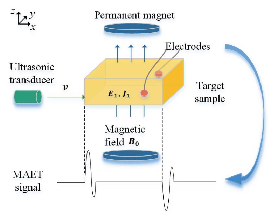
Magneto-acousto-electrical tomography (MAET) is an imaging method generating a source current under excitation of both static magnetic field and acoustic field, and electrodes are used to detect the electrical signal to further reconstruct conductivity image. Previous studies ignored the non-uniformity of magnetic field. However, the reconstructed image will introduce artifacts due to magnetic field inhomogeneity, which is small but cannot be neglected. We analyzed the characteristics of magneto-acousto-electrical signal under uniform and inhomogeneous magnetic fields in simulation. This paper deduces the relation of magneto-acoustic signal generated by inhomogeneous static magnetic field, and reconstructed conductivity image under non-uniform static magnetic field through synthetic aperture imaging. Furthermore, to verify the validity of the theory, an experimental platform was built to reconstruct the conductivity of phantom. In clinical applications, non-uniform static magnetic field can achieve a fully open magnetic field structure, which is much more friendly for inspection of patients with autism and even children. Permanent magnets that generate non-uniform static magnetic fields have the advantages of smaller size, lighter weight, and lower cost than magnets that generate uniform static magnetic field, which can effectively optimize equipment space.
Magneto-Acousto-Electrical Tomography Based on Synthetic Aperture with Inhomogeneous Static Magnetic Field
2024-03-12
PIER M
Vol. 125, 51-61, 2024
download: 265
An Adaptive Mesh Global Modeling Method for Solving Non-Ideal Sliding Electrical Contact Problems
Jian Sun , Junsheng Cheng , Ling Xiong , Yuantao Cong and Heyang Wang
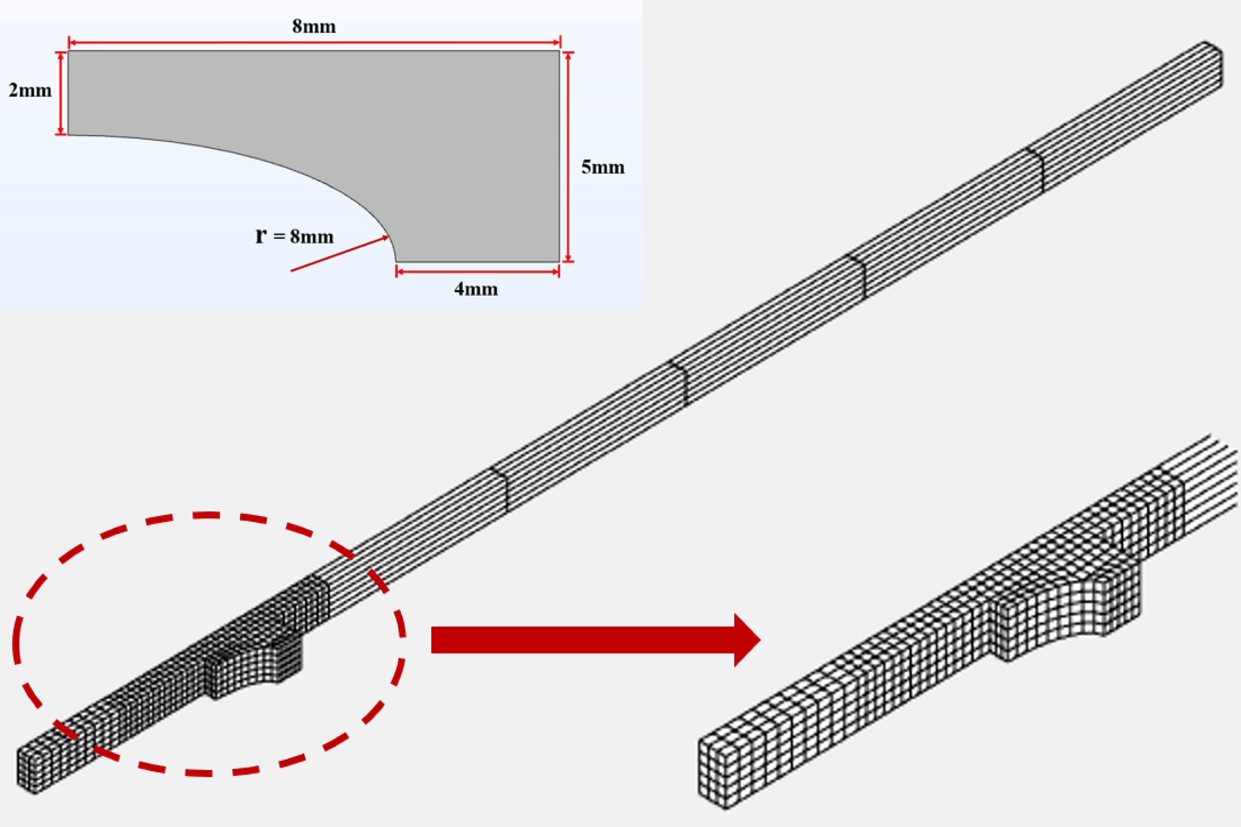
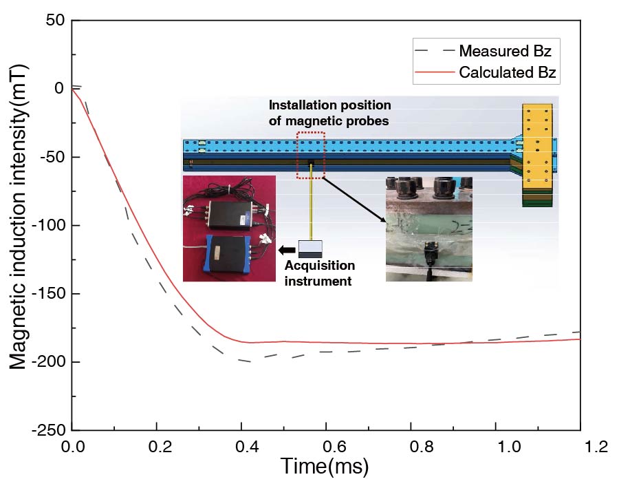
The armature and rail sizes of electromagnetic rail launcher vary greatly, and the refined 3D finite element computation occupies a large amount of physical memory. In order to enhance the economy of dynamic computation, this paper proposes an adaptive hexahedral mesh method based on mesh expansion, compression and translation. In addition, split nodes are used on both sides of the contact surface, and interface conditions and frictional heat sources are constrained through point penalty function method to solve non-ideal sliding electrical contact problems. Comparative calculations with the same type of software and the same model are carried out, and the results calculated in this paper are consistent with the relevant results of MEAP3D. This paper also compares the EMRL calculation results of adaptive mesh model and constant mesh model to verify the reliability of the method. In addition, the C-type EMRLs are compared and analyzed. The results show that due to the influence of velocity skin effect, the dynamic inductance gradient of the rail gradually increases over time and is greater than the static value. The maximum difference between the two is 5.65% of the dynamic inductance gradient. The steel shell generates eddy currents, causing a decrease in armature velocity of 4.7 m/s under the small caliber launcher. The maximum eddy current density waveform of the shell exhibits two peaks. In the frictionless heat, the temperature of the armature is underestimated, and under the action of frictional heat, the trailing edge of the armature is ablated and melted.
An Adaptive Mesh Global Modeling Method for Solving Non-ideal Sliding Electrical Contact Problems
2024-03-11
PIER M
Vol. 125, 41-49, 2024
download: 302
Analysis and Design of a Directive Antenna Array for C-Band Communication Applications
Ayman Elboushi , Anwer S. Abd El-Hameed , Sulaiman Alsuwailem and Eman Gamal Ouf
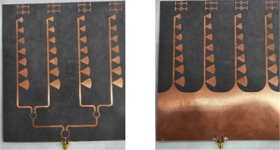
Three scenarios of high gain bow-tie based antenna array systems are introduced and investigated in this paper. The proposed designs are intended for integration as Tx/Rx antennas in C-band communication systems. Wide operating bandwidth and consistent radiation characteristics over the frequency range from 4 GHz to 5 GHz are defined for the three configurations. A two-stage Wilkinson power divider provides the feed mechanism for the proposed array. The initial structure has four radiating elements, each incorporating seven bow-tie dipoles arranged in a printed Log-Periodic Directional Array (PLPDA) configuration. The gain of the second and third designs is improved by adding resonators in front of the array elements. Furthermore, the second design features triangular-shaped resonators, while the third design employs H-shaped resonators. The designs are simulated and optimized using HFSS and CSTMWS software, and subsequently, they are fabricated using the photolithography technique. The initial design demonstrates an experimental bandwidth from 3.7 GHz to 5.1 GHz and achieves a measured gain of 13.8 dBi at 4.7 GHz. The second and third configurations operate in the frequency bands of 4.3 GHz to 5.3 GHz and 3.7 GHz to 5 GHz, respectively, exhibiting measured gains of 14.1 dBi and 15 dBi. The overall dimensions of the proposed arrays are kept within reasonable limits, with the first array being 2.51λ × 2.74λ, the second being 2.09λ × 2.82λ, and the third being 2.51λ × 2.97λ. The three array designs can be considered as good candidates for C-band communication applications.
Analysis and Design of a Directive Antenna Array for C-band Communication Applications
2024-03-11
PIER M
Vol. 125, 31-40, 2024
download: 313
Electromagnetic-Thermal Modeling of Multi-Turn Electromagnetic Rail Launcher with Phase Transition
Jian Sun , Ling Xiong , Yuantao Cong and Junsheng Cheng
Electromagnetic thermal performance is critical during electromagnetic launch. However, due to the harsh in-bore environment, it is difficult to obtain multi-parameter information by means of experimental measurement, which further limits our understanding of the field distribution of electromagnetic launcher. In this paper, considering the temperature dependence of material conductivity and armature solid-liquid isothermal phase transition, a bidirectional coupling model of electro-magnetic-thermal field of multi-turn electromagnetic rail launcher is established. The reliability of this model is verified by comparing the calculation results of the same model and input conditions with the numerical tool EMAP3D, as well as the related experimental comparison. In addition, the multi-turn and traditional EMRLs are compared and analyzed. The results show that compared to single-turn EMRL, the armatures have greater driving force in two multi-turn configurations, and the impulse lifting rates are about 1/2. In the multi-turn configurations, the lateral resultant forces of the two armatures are not zero, while the lateral force difference in the integrated negative rail configuration is relatively small. The ablation of the armature in the integrated negative rail configuration is less severe.
Electromagnetic-Thermal Modeling of Multi-Turn Electromagnetic Rail Launcher with Phase Transition
2024-03-09
PIER M
Vol. 125, 21-29, 2024
download: 330
Analytical Model of Six-Pole Axial-Radial Active Magnetic Bearing Based on Flux Density and Segmentation of Magnetic Field
Huangqiu Zhu , Zhen Wang and Gai Liu
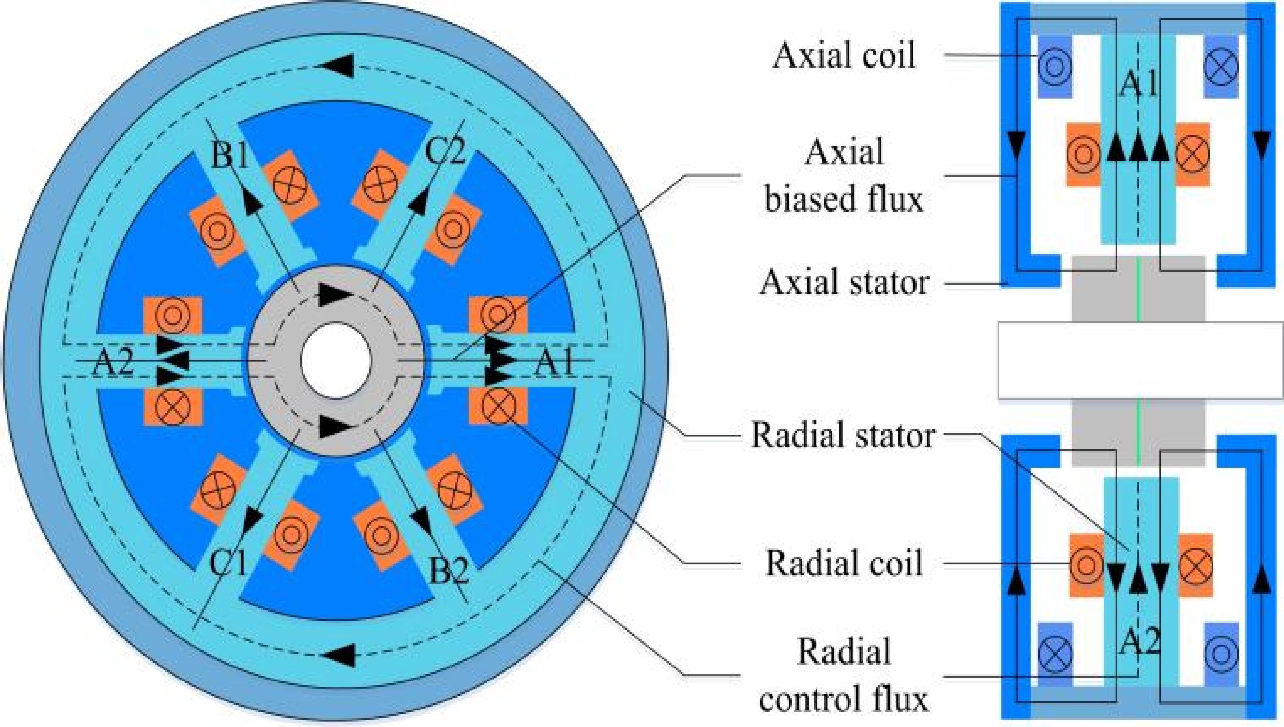
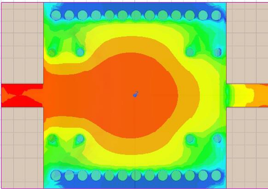
To reduce the coupling resulting from structural asymmetry and enhance the load-bearing capacity per unit area, a six-pole axial-radial active magnetic bearing (AR-AMB) has been suggested. To refine the precision of the mathematical model derived from the conventional equivalent magnetic circuit model, a modeling technique that employs the flux density and magnetic field segmentation has been proposed. Firstly, the structure and operational principle of the six-pole AR-AMB are introduced. Subsequently, an improved model based on the flux density is established by considering the internal relationship between the iron core and air gap magnetic field in a magnetic bearing with pole shoes. The model addresses issues related to the accurate calculation of fringing magnetic flux and magnetic saturation of core materials while accounting for eddy current effects on suspension force. Finally, the accuracy of the theoretical analysis results has been validated through finite element simulation and experiment, and demonstrated that the rotor based on this model exhibits robust anti-interference capabilities.
Analytical Model of Six-pole Axial-radial Active Magnetic Bearing Based on Flux Density and Segmentation of Magnetic Field
2024-03-08
PIER M
Vol. 125, 11-19, 2024
download: 375
Customizable Substrate Integrated Waveguide Based Dual Pole Band Pass Filter for X Band Application
Ruchi Paliwal , Shweta Srivastava and Reema Budhiraja
This manuscript introduces an innovative customizable dual pole bandpass filter using a substrate-integrated waveguide technology on a conventional Rogers RT/Duroid 5880 high-frequency laminate. This structure is bifurcated into two identical cavity resonators to get the band stop-band pass-band stop behavior. The structure comprises lumped capacitors to indicate each resonator's operating frequency. Additionally, altering the capacitors in the proposed design facilitates the generation of the tunable dual pole in passband frequency, adding to its versatility. Further, measured and simulated results indicate that the design attains large tuning bandwidth, excellent insertion loss (better than 0.4 dB) and return loss (>22 dB), high Q-factor (11.8 to 16.87) with fractional bandwidth of 4.8% to 8.9% throughout the tuning range, affirming its practicality and functionality in X-band. A total of 12.3% of tunability is achieved from the structure.
Customizable Substrate Integrated Waveguide Based Dual Pole Band Pass Filter for X Band Application
2024-03-08
PIER M
Vol. 125, 1-9, 2024
download: 384
A Compact Loop-Shaped Dual-Band Omnidirectional Rectenna for RF Energy Harvesting
Lei Li , Ruifeng Xu , Jingxu Cao , Xue Li and Jingchang Nan
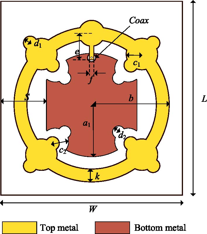
This paper presents a compact loop-shaped omnidirectional rectenna for RF energy harvesting at 2.45 GHz and 5.8 GHz. Firstly, a loop-shaped antenna with iterated circular concave and convex structures is proposed to operate at both frequencies. Then, a rectifier circuit uses a complex impedance correlation matching technique to achieve high conversion efficiency. By connecting a piece of microstrip, two uncorrelated input impedances are transformed into a pair of conjugate impedances. In addition, by using a π-shaped structure with the same equivalent characteristic impedance and complementary equivalent electrical lengths at both frequencies, the pair of conjugate impedances are simultaneously matched to 50 Ω. The rectifier circuit is integrated in the loop-shaped antenna to form a compact dual-band rectenna. The overall size of the rectenna is 67.5 mm x 71.5 mm x 1.016 mm. The test results show that the S11 of the antenna is -13.5 dB and -18.7 dB, and the peak conversion efficiencies of the rectenna are 65.1% and 38.4% at 2.45 GHz and 5.8 GHz, respectively. The simulated and tested results are quite similar.
A Compact Loop-shaped Dual-band Omnidirectional Rectenna for RF Energy Harvesting