Vol. 71
Latest Volume
All Volumes
PIERC 143 [2024] PIERC 142 [2024] PIERC 141 [2024] PIERC 140 [2024] PIERC 139 [2024] PIERC 138 [2023] PIERC 137 [2023] PIERC 136 [2023] PIERC 135 [2023] PIERC 134 [2023] PIERC 133 [2023] PIERC 132 [2023] PIERC 131 [2023] PIERC 130 [2023] PIERC 129 [2023] PIERC 128 [2023] PIERC 127 [2022] PIERC 126 [2022] PIERC 125 [2022] PIERC 124 [2022] PIERC 123 [2022] PIERC 122 [2022] PIERC 121 [2022] PIERC 120 [2022] PIERC 119 [2022] PIERC 118 [2022] PIERC 117 [2021] PIERC 116 [2021] PIERC 115 [2021] PIERC 114 [2021] PIERC 113 [2021] PIERC 112 [2021] PIERC 111 [2021] PIERC 110 [2021] PIERC 109 [2021] PIERC 108 [2021] PIERC 107 [2021] PIERC 106 [2020] PIERC 105 [2020] PIERC 104 [2020] PIERC 103 [2020] PIERC 102 [2020] PIERC 101 [2020] PIERC 100 [2020] PIERC 99 [2020] PIERC 98 [2020] PIERC 97 [2019] PIERC 96 [2019] PIERC 95 [2019] PIERC 94 [2019] PIERC 93 [2019] PIERC 92 [2019] PIERC 91 [2019] PIERC 90 [2019] PIERC 89 [2019] PIERC 88 [2018] PIERC 87 [2018] PIERC 86 [2018] PIERC 85 [2018] PIERC 84 [2018] PIERC 83 [2018] PIERC 82 [2018] PIERC 81 [2018] PIERC 80 [2018] PIERC 79 [2017] PIERC 78 [2017] PIERC 77 [2017] PIERC 76 [2017] PIERC 75 [2017] PIERC 74 [2017] PIERC 73 [2017] PIERC 72 [2017] PIERC 71 [2017] PIERC 70 [2016] PIERC 69 [2016] PIERC 68 [2016] PIERC 67 [2016] PIERC 66 [2016] PIERC 65 [2016] PIERC 64 [2016] PIERC 63 [2016] PIERC 62 [2016] PIERC 61 [2016] PIERC 60 [2015] PIERC 59 [2015] PIERC 58 [2015] PIERC 57 [2015] PIERC 56 [2015] PIERC 55 [2014] PIERC 54 [2014] PIERC 53 [2014] PIERC 52 [2014] PIERC 51 [2014] PIERC 50 [2014] PIERC 49 [2014] PIERC 48 [2014] PIERC 47 [2014] PIERC 46 [2014] PIERC 45 [2013] PIERC 44 [2013] PIERC 43 [2013] PIERC 42 [2013] PIERC 41 [2013] PIERC 40 [2013] PIERC 39 [2013] PIERC 38 [2013] PIERC 37 [2013] PIERC 36 [2013] PIERC 35 [2013] PIERC 34 [2013] PIERC 33 [2012] PIERC 32 [2012] PIERC 31 [2012] PIERC 30 [2012] PIERC 29 [2012] PIERC 28 [2012] PIERC 27 [2012] PIERC 26 [2012] PIERC 25 [2012] PIERC 24 [2011] PIERC 23 [2011] PIERC 22 [2011] PIERC 21 [2011] PIERC 20 [2011] PIERC 19 [2011] PIERC 18 [2011] PIERC 17 [2010] PIERC 16 [2010] PIERC 15 [2010] PIERC 14 [2010] PIERC 13 [2010] PIERC 12 [2010] PIERC 11 [2009] PIERC 10 [2009] PIERC 9 [2009] PIERC 8 [2009] PIERC 7 [2009] PIERC 6 [2009] PIERC 5 [2008] PIERC 4 [2008] PIERC 3 [2008] PIERC 2 [2008] PIERC 1 [2008]
2017-02-27
PIER C
Vol. 71, 177-187, 2017
download: 247
Compact Dual-Mode Microstrip Bandpass Filters with Transmission Zeros Using Modified Star Shaped Resonator
Kenganahalli Gowdra Avinash and Inabathini Srinivasa Rao
A modified star-shaped dual-mode microstrip loop resonator with a triangular patch is proposed to design compact narrow band bandpass filters with transmission zeros. The triangular patch is used as perturbation element to couple degenerated modes. The position of transmission zeros can be tuned by varying the size and location of the perturbation element. The coupling mechanism (inductive or capacitive) and the type of input/output feed (orthogonal or non-orthogonal) determine the type of filter response like symmetric or asymmetric. Three highly selective two-pole narrow band bandpass filters are designed using a modified star-shaped resonator with tunable transmission zeros. First, two filters with non-orthogonal feed lines have an asymmetric response with transmission zeros on one side of the passband, whereas the third filter with orthogonal feed lines exhibits symmetric frequency response with transmission zeros on both sides of the passband. Even and odd mode analysis is applied to the dual mode filters to calculate the position of transmission zeros. Filters are realized using a low loss dielectric substrate, and measured results are in good agreement with the theoretical and simulated ones.
COMPACT DUAL-MODE MICROSTRIP BANDPASS FILTERS WITH TRANSMISSION ZEROS USING MODIFIED STAR SHAPED RESONATOR
2017-02-25
PIER C
Vol. 71, 169-175, 2017
download: 253
Maple Leaf Shaped UWB Monopole Antenna with Dual Band Notch Functionality
Amjad Iqbal , Omar A. Saraereh and Sushil K. Jaiswal
A sharply rejected dual notch band UWB monopole antenna is presented in this paper. The proposed antenna consists of maple leaf shaped radiating element, a 50 Ω microstrip feed line and truncated ground plane. The proposed antenna shows the UWB operation in the frequency range (1.7 GHz-11.1 GHz) with VSWR<2 except the notch bands and two band notches centered at 4.3 GHz and 7.7 GHz. The band notches are achieved by introducing a meandered slot in the radiating element and U-shaped slot in feed line. The substrate used for designing of UWB antenna is low loss Rogers 5880 having relative permittivity of 2.2. The novelty of the proposed antenna is its shape and ability to support UWB bandwidth requirements, and it also rejects two bands to avoid possible interference with existing communication system. Good agreement between the simulated and measured results is observed. The proposed antenna has good gain and efficiency at pass bands.
MAPLE LEAF SHAPED UWB MONOPOLE ANTENNA WITH DUAL BAND NOTCH FUNCTIONALITY
2017-02-23
PIER C
Vol. 71, 161-168, 2017
download: 282
Small Transmit-Receive Frequency Space Filtering Duplex Patch Antenna Array with High Isolation
Xian Jing Lin , Ze-Ming Xie and Pei Sheng Zhang
In this paper, a 2 x 1 duplex antenna array with small frequency space and high isolation between transmitting and receiving bands is presented. The duplex antenna array element consists of a pair of radiating patches for bidirectional radiation, a set of microstrip resonator and H-slot resonator coupled to the patches for transmitting, and the other set of microstrip and H-slot resonators coupled to the patches for receiving. The H slots are designed for the operations of coupling and the elements of the bandpass filters. The two antenna elements of the 2 x 1 array are connected by transmitting and receiving channels microstrip power-split resonators. The array achieves a compact size and high performances in terms of high isolation and small Tx-Rx frequency space. Higher than 30 dB and 40 dB ports isolation at 1.94-1.99 GHz and 2.43-2.52 GHz is realized. And the Tx-Rx frequency space Δf=(fr-ft) is smaller than 0.23 times of the central frequency (fr+ft)/2.
SMALL TRANSMIT-RECEIVE FREQUENCY SPACE FILTERING DUPLEX PATCH ANTENNA ARRAY WITH HIGH ISOLATION
2017-02-20
PIER C
Vol. 71, 149-159, 2017
download: 269
Printed Meander Line MIMO Antenna Integrated with Air Gap, DGS and RIS: a Low Mutual Coupling Design for LTE Applications
Shahanawaz Kamal and Anjali Ashish Chaudhari
Multiple-input and multiple-output (MIMO) is currently regarded as a key technology for long term evolution (LTE), but a critical effect is mutual coupling (S21) due to space constraint in miniaturized design. A compact-size antenna with low mutual coupling will be an ideal choice for better system performance. This paper describes the design of a small-size (48 × 48 mm2) MIMO antenna system with low mutual coupling for LTE 800 MHz applications. The antenna system comprises two FR-4 substrate layers; one printed with two meander line antennas (MLAs) and the other printed with reactive impedance surface (RIS) and defected ground structure (DGS). The properties of the antenna, such as S-Parameters, excited surface current distribution, far-field radiation pattern and diversity performance characteristics, were studied. The results indicated that MLAs rendered compactness to the system. Introduction of air gap (AG) between the two substrates, DGS and periodic square patches of RIS resulted in 452 MHz bandwidth and mutual coupling of -41.18 dB between antenna elements. The performance of the proposed design compared with other reported geometry has been demonstrated. Parameters including bandwidth, ratio of antenna area/improvement in S21, antenna efficiency and the envelope correlation coefficient were compared. Considering the results, the present system appears to be comparatively more efficient.
PRINTED MEANDER LINE MIMO ANTENNA INTEGRATED WITH AIR GAP, DGS AND RIS: A LOW MUTUAL COUPLING DESIGN FOR LTE APPLICATIONS
2017-02-17
PIER C
Vol. 71, 141-148, 2017
download: 288
Compact Wide-Beam Circularly Polarized Antenna with Stepped Arc-Shaped Arms for CNSS Application
Can Wang , Fushun Zhang , Fan Zhang , Ya-Li Yao and Tian Li
A single-feed circularly polarized wide-beam antenna is proposed for Compass Navigation Satellite System (CNSS) application. The antenna consists of four stepped arc-shaped arms, which are applied to generate circularly polarized radiation. To broaden the beamwidth, each arm is split up into two horizontal arc-shaped parts and one vertical part. The proposed antenna is simulated, fabricated and tested. The measured results show that the 10-dB return loss band of the proposed antenna is from 2.37 GHz to 2.65 GHz and the 3-dB axial ratio band from 2.42 GHz to 2.55 GHz, covering the receiving band (2.49175 GHz ± 4.08 MHz) of CNSS. Its 3-dB AR beamwidth is 181° at 2.491 GHz. For the horizontal radiation pattern of the proposed antenna at 5° elevation angle, the RHCP gain is greater than -1.1 dBic, and the out-of-roundness is 1 dB. Additionally, the proposed antenna has a size of 0.37λ0×0.37λ0×0.11λ0 with respect to 2.491 GHz.
COMPACT WIDE-BEAM CIRCULARLY POLARIZED ANTENNA WITH STEPPED ARC-SHAPED ARMS FOR CNSS APPLICATION
2017-02-13
PIER C
Vol. 71, 133-140, 2017
download: 257
Triple-Band Composite Right/Left Handed Bandpass Filter Using a New Circular Inter-Digital Capacitor for Wireless Applications
Ashish Kumar , Dilip Kumar Choudhary and Raghvendra Kumar Chaudhary
In this paper, a compact triple-band bandpass filter based on composite right/left handed (CRLH) approach has been proposed. The zeroth order resonance (ZOR) frequency of the designed filter can be controlled effectively by varying the series parameters. A new circular interdigital capacitor is integrated to provide series capacitance. The number of passbands depends on number of rings of circular interdigital capacitor (C-IDC). In order to validate metamaterial behavior, a dispersion diagram has been plotted for the designed filter. The proposed filter offers measured 3dB fractional bandwidth of 71% at 1.7 GHz, 24% at 2.9 GHz and 12% at 4.1 GHz as center frequencies. The designed filter will be suitable for different wireless applications such as global navigation satellite systems (1.559-1.610 GHz), GSM1800, indoor femtocells (2.5-2.7 GHz), air traffic surveillance (2.7-2.9 GHz) and fixed satellite services (3.8-4.2 GHz). The size of the proposed filter is 0.13λ0 × 0.11λ0, where λ0 is the free space wavelength at ZOR frequency of 1.7 GHz.
TRIPLE-BAND COMPOSITE RIGHT/LEFT HANDED BANDPASS FILTER USING A NEW CIRCULAR INTER-DIGITAL CAPACITOR FOR WIRELESS APPLICATIONS
2017-02-12
PIER C
Vol. 71, 123-131, 2017
download: 398
Wideband Metamaterial Solar Cell Antenna for 5 GHz Wi-Fi Communication
Michael Elsdon , Okan Yurduseven and Xuewu Dai
In this paper, a novel design for a wideband integrated photovoltaic (PV) solar cell patch antenna for 5 GHz Wi-Fi communication is presented and discussed. The design consists of a slot loaded patch antenna with an array of complimentary split ring resonators (cSRR) etched in the ground plane. This is then integrated with a solar cell element placed above the patch, where the ground plane of the solar cell acts as a stacked antenna element from an RF perspective. The design is simulated on CST Microwave Studio and fabricated. The results indicate that an impedance bandwidth of 1 GHz is achieved to cover the 5 GHz Wi-Fi band with a gain of between 7.73 dBi and 8.18 dBi across this band. It is also demonstrated that size reduction of up to 25% can be achieved. Moreover, it is noted that using a metamaterial loaded ground plane acts as an impedance transformer, therefore the antenna can be fed directly with a 50 Ω microstrip feed line, hence further reducing the overall size.
WIDEBAND METAMATERIAL SOLAR CELL ANTENNA FOR 5 GHZ WI-FI COMMUNICATION
2017-02-09
PIER C
Vol. 71, 111-122, 2017
download: 258
Ultra-Compact Microstrip Antenna Array and Miniaturized Feeding Network
Wei Qiao , Xi Gao , Xingyang Yu , Si Min Li , Yan-Nan Jiang and Hui-Feng Ma
In this paper, an interdigital resonator that can greatly decrease mutual coupling between adjacent patches is proposed to realize an ultra-compact microstrip antenna array operating in 2.4 GHz wireless communication system. Due to its remarkable performance of decoupling, the edge to edge distance between adjacent patches can be reduced to 0.08λ0 and even less. Meanwhile, a miniaturized feeding network, which is composed of a CRLH-TL-based phase shifter and T-junction-based power divider, is used to feedthe compact antenna array. The simulation results show that the proposed antenna array has an impedance bandwidth of 8.34%. We fabricate the antenna array to verify its performance. The experimental results are in good agreements with the simulations. Compared to the published designs, the proposed antenna array hasanultra-compact structure and hence can be used in space limited communication systems.
ULTRA-COMPACT MICROSTRIP ANTENNA ARRAY AND MINIATURIZED FEEDING NETWORK
2017-02-08
PIER C
Vol. 71, 101-109, 2017
download: 483
A Novel Tunable Microstrip Patch Antenna Using Liquid Crystal
Jia-Wei Dai , Hong-Li Peng , Yao-Ping Zhang and Jun-Fa Mao
This paper presents a novel tunable microstrip patch antenna using liquid crystal. It adopts a differentially-driven, aperture-coupled, and stacked-patch structure. Compared with the conventional design, this novel antenna achieves a larger frequency tuning range, much wider impedance bandwidth, higher radiation efficiency and gain. Besides, the novel antenna facilitates the bias design as the bias signal is naturally isolated from the RF signal. Both the conventional and novel antennas are designed to operate at 28 GHz using an RT/Duroid 5880 substrate and K15 liquid crystal. Results show that the novel antenna has a tuning range of 3.1%, an impedance bandwidth of 6.43%, a peak radiation efficiency of 70%, and a peak realized gain of 6.5 dBi, while the conventional antenna has the tuning range of 2.7%, impedance bandwidth of 3.57%, peak radiation efficiency of 45%, and peak realized peak gain of 4.5 dBi.
A NOVEL TUNABLE MICROSTRIP PATCH ANTENNA USING LIQUID CRYSTAL
2017-02-03
PIER C
Vol. 71, 91-100, 2017
download: 289
Design of Compact Reconfigurable Broadband Band-Stop Filter Based on a Low-Pass Filter Using Half Circle DGS Resonator and Multi-Layer Technique
Ahmed Boutejdar
This paper describes the design of a two-pole low-pass and band-stop filters. The low-pass structure is designed at the cutoff frequency of 2 GHz for the L-band applications. This architecture uses half circle defected ground structure HCDGS instead full circle DGS resonator. Both the HCDGS shapes are etched in the ground plane and coupled via a substrate with a compensated capacitor. The rejection bandwidth of the LPF covers a large wideband spectrum. Therefore, the band suppression reaches more than 3fc. The filter is simulated and fabricated. The measured results are in good agreement with the full-wave simulated ones, showing the merits of compact size and sharp roll-off. The multi-layer technique has been used, In order to realize a transformation from low-pass behaviours to band-stop characteristics, keeping the same passband features. The new extracted band-stop topology is simulated and optimized using an RO4003 substrate with dielectric constant of 3.38 and thickness of h = 0.813 mm. The structure has a wide stopband with over 20 dB rejection from 11 to 20 GHz. Such filters can be used for L-band and military applications.
DESIGN OF COMPACT RECONFIGURABLE BROADBAND BAND-STOP FILTER BASED ON A LOW-PASS FILTER USING HALF CIRCLE DGS RESONATOR AND MULTI-LAYER TECHNIQUE
2017-02-02
PIER C
Vol. 71, 79-89, 2017
download: 289
Enhanced Low Profile, Dual-Band Antenna via Novel Electromagnetic Band Gap Structure
Mohammad El Ghabzouri , Abdenacer Es Salhi , Pedro Anacleto and Paulo Mendes
This paper presents a dual-band, low profile antenna with reduced specific absorption rate (SAR) for mobile handset applications. Here, dual-band operation is obtained by combining a printed dipole antenna (initially resonating at 4.3 GHz) with EBG mushroom-like structures loaded with circular slots (CS). The final structure operates at 3.44 GHz (additional band required for LTE Advanced LTE-A) and 4.5 GHz (for Smartphone WLAN applications) with improved bandwidth and reflection coefficient (350-MHz around 3.5 GHz with -26 dB, and 330 MHz around 4.5 GHz with -30 dB). Finally, a dosimetry study of the proposed printed dual-band dipole antenna is presented and verifies an SAR reduction from 9 W/Kg to 1.41W/Kg compared to the same antenna without any loading structure, and from 3.98 W/Kg to 1.41 W/Kg compared to a standard EBG mushroom-like structure.
ENHANCED LOW PROFILE, DUAL-BAND ANTENNA VIA NOVEL ELECTROMAGNETIC BAND GAP STRUCTURE
2017-01-30
PIER C
Vol. 71, 69-77, 2017
download: 266
A Dual Band Slot Antenna for Wireless Applications with Circular Polarization
Azadeh Pirooj , Mohammad Naser-Moghadasi , Ferdows B. Zarrabi and Alireza Sharifi
In recently developed wireless communication systems, circular polarization (CP) antennas are used for communication links to reduce the natural loss effect in receivers. Therefore, in this paper, a dual-band microstrip slot antenna based on a parallel split ring resonator with circular and linear polarization which can be used for wireless and WiMAX applications is presented. The final antenna to design is based on inspired split ring resonators (SRR) to achieve circular polarization and compact size and with special parallel form of the SRR and straight feed line. We have achieved higher bandwidth in the requested frequency range with dual-band characteristics. The final antenna has a bidirectional pattern with circular polarization at the range of 2.9-3.65 GHz and bandwidths of 2-3.6 and 3.8-4.8 GHz with VSWR<2 for WLAN, Bluetooth and radar applications for IEEE WLAN protocol with gain of 5-6 dBi, respectively. The size of the prototype patch antenna is 40×40 mm2. It is designed and fabricated on an FR-4 low cost substrate with εr=4.4 and a thickness of 1.6 mm. It is simulated using HFSS full wave software. In addition, the experimental results are presented and compared with simulation for VSWR, radiation patterns and axial ratio. The periodic analysis has been used for extracting the metamaterial parameters.
A DUAL BAND SLOT ANTENNA FOR WIRELESS APPLICATIONS WITH CIRCULAR POLARIZATION
2017-01-27
PIER C
Vol. 71, 59-67, 2017
download: 366
A Broadband Planar Quasi-Yagi Antenna with a Modified Bow-Tie Driverfor Multi-Band 3G/4G Applications
Tinghui Zhao , Yang Xiong , Xian Yu , Haihua Chen , Ming He , Lu Ji , Xu Zhang , Xinjie Zhao , Hongwei Yue and Fangjing Hu
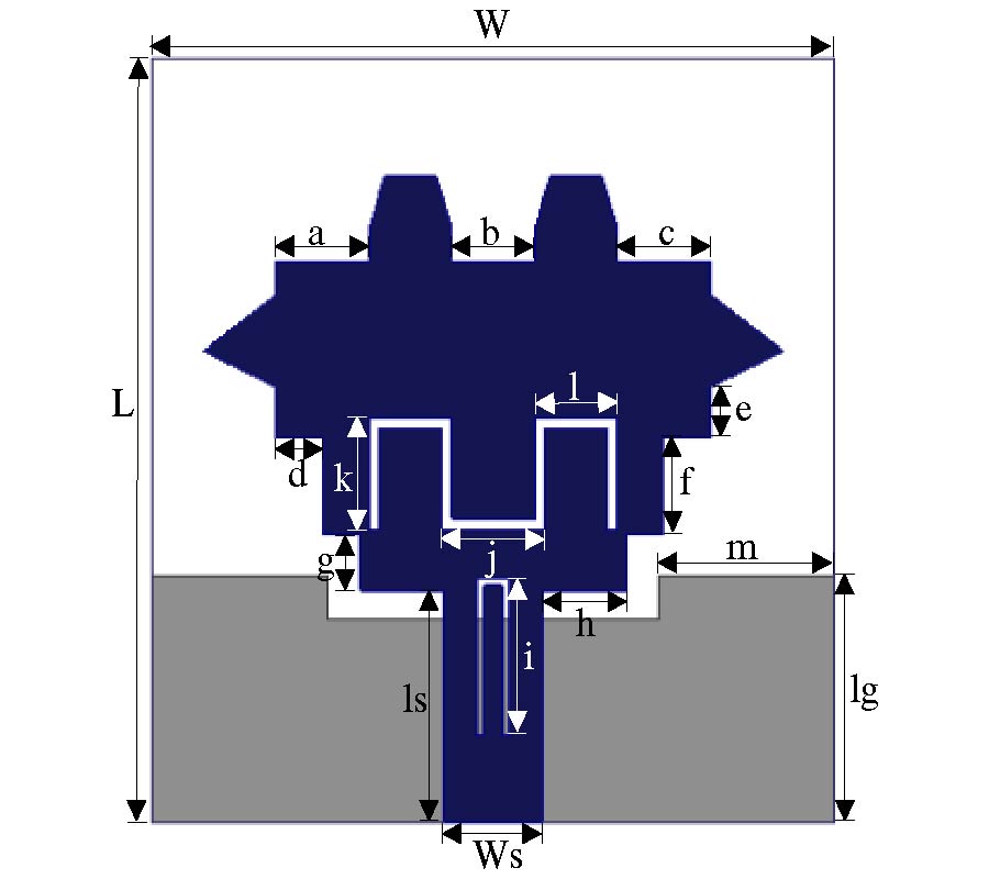
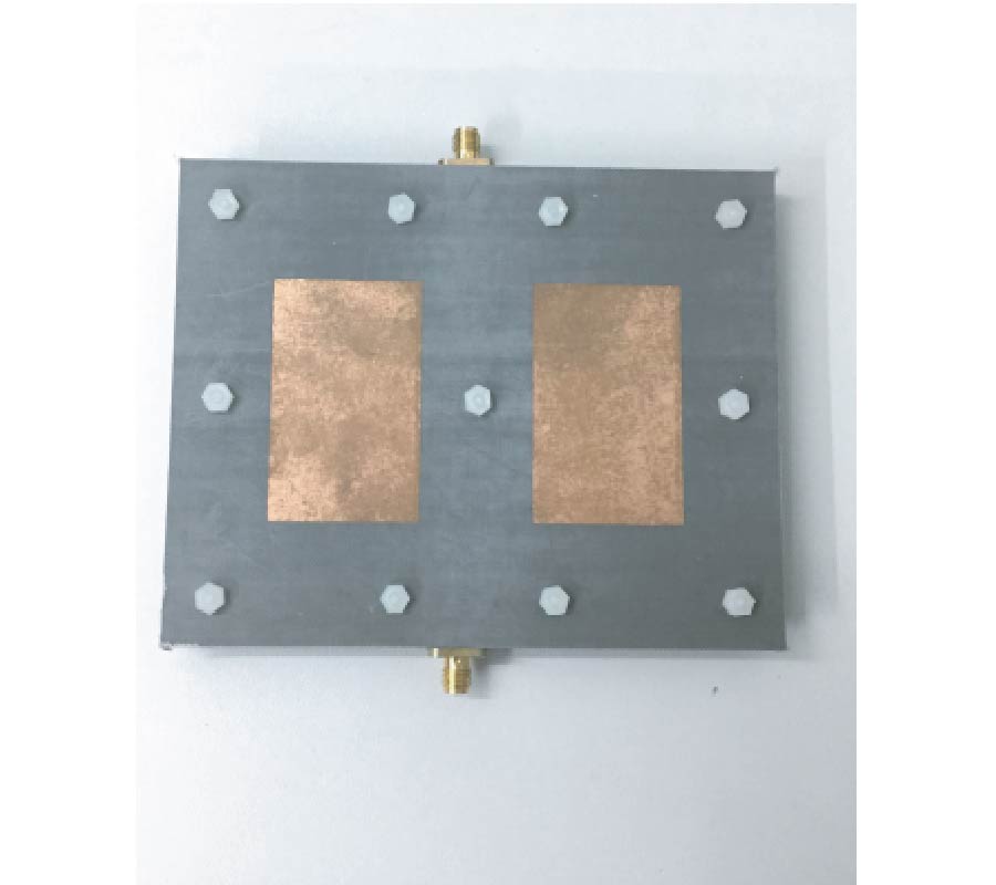
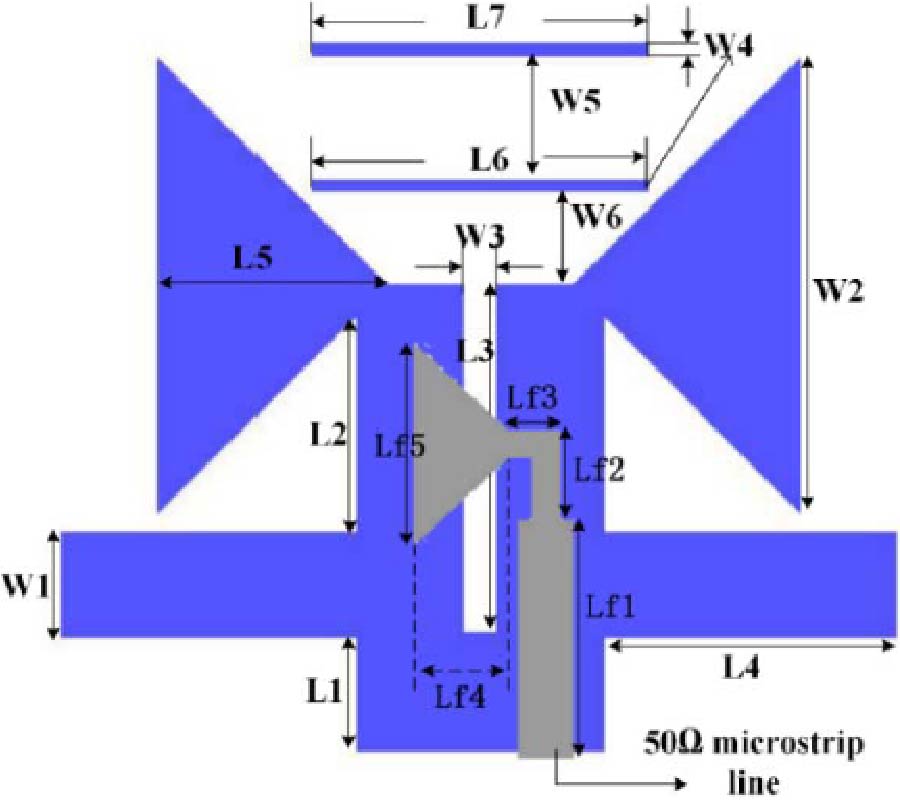
This paper presents a broadband and compact planar quasi-Yagi antenna for multi-band 3G/4G applications.The proposed quasi-Yagi antenna consists of a modified bow-tie driver to increase the bandwidth, a passive reflector and two passive directors to enhance the directivity at the lower and higher ends of the operating band, respectively. A microstrip-to-slotline transition feed is used to achieve a good impedance matching. It is confirmed by experiment that general approaches for increasing the bandwidth of bow-tie antennas are also feasible for quasi-Yagi antennas with bow-tie drivers. Furthermore, with the modified bow-tie structure, the directivity of the antenna at higher frequencies of the operating band is enhanced, because the bow-tie shape can form planar horn structures and has strong current distributions at high frequencies. The proposed antenna is fabricated using an FR4 substrate with a dielectric constant of 4.2, and the overall dimension of the antenna is 1.24λgc×0.94λgc. Measurements show that the 10 dB return loss bandwidth is 80.4%, operating from 1.45 to 3.4 GHz. Measured gains are greater than 4 dBi within the entire bandwidth, and the front-to-back ratios are greater than 10 dB. Having a multi-band coverage within the 3G/4G spectra,this antenna is expected to be used for 3G/4G mobile wireless communications.
A BROADBAND PLANAR QUASI-YAGI ANTENNA WITH A MODIFIED BOW-TIE DRIVERFOR MULTI-BAND 3G/4G APPLICATIONS
2017-01-26
PIER C
Vol. 71, 51-58, 2017
download: 300
Highly Intergrated X-Band LTCC Receiver Module
Bo Zhou , Qiang Ma , Qipeng Wang , Liwei Yan , Na Zhou and Chong-Hu Cheng
A highly integrated X-band receiver module is designed based on a 10-layered low temperature co-fired ceramic (LTCC) substrate. A compact X-band bandpass filter (BPF), an intermediate frequency (IF) band hybrid and an IF band BPF are proposed for the receiver module. The measured gain parameter of the proposed receiver is higher than 51 dB, and noise figure (NF) and image rejection are better than 2.5 dB and 37 dB, respectively. The overall size of the receiver module is only 54 mm × 15 mm × 1 mm. Comparisons and discussions are also provided.
HIGHLY INTERGRATED X-BAND LTCC RECEIVER MODULE
2017-01-26
PIER C
Vol. 71, 41-49, 2017
download: 254
Compact 1×2 and 2×2 MIMO Antennas with Enhanced Isolation for Ultrawideband Application
Hui Li , Jinhai Liu , Ziyang Wang and Ying-Zeng Yin
Two small size multiple-input-multiple-out (MIMO) antennas with high isolation for ultrawideband (UWB) applications are presented. A two-element MIMO antenna, which is mounted on an FR4 substrate with a compact size of 24 mm × 33 mm, consists of two symmetric circular monopole elements and a modified ground. The protruded ground provides a way to improve isolation and impedance matching. Such a wide band from 2.75 to 11 GHz is achieved by using modified ground technology, and high isolation more than 20 dB is also accomplished. Meanwhile, moderate gain and omnidirectional radiation patterns can be obtained. Based on the circular monopole with modified ground, a four-element antenna array is also constructed and studied. The size of the four-element antenna with orthogonal arrangement is 44 mm × 44 mm. Measured results show that the antenna also exhibits good impedance matching as well as low envelope correlation coefficient over the entire UWB spectrum.
COMPACT 1×2 AND 2×2 MIMO ANTENNAS WITH ENHANCED ISOLATION FOR ULTRAWIDEBAND APPLICATION
2017-01-18
PIER C
Vol. 71, 33-40, 2017
download: 344
Wideband Quasi-Yagi Antenna Design and Its Usage in MIMO/Diversity Applications
Li Gu , Yan-Wen Zhao , Qiang-Ming Cai and Zhi-Peng Zhang
In this paper, a novel wideband quasi-Yagi antenna is proposed and investigated for multiple-input multiple-output (MIMO)/diversity antennas applications. An aperture-coupled balun is adopted with a curved Yagi radiator for the antenna to realize wideband property. The proposed quasi-Yagi antenna has high radiation efficiency and stable end-fire radiation patterns, operating in a wide bandwidth from 7 to 13.8 GHz. Then a pattern diversity antenna is developed using two elements, which are overlapped partly and placed in opposite orientations. The measured 10-dB bandwidth of the MIMO antenna is from 6.3 to 13.6 GHz. Meanwhile, isolation between the two ports is better than -26 dB. The radiation patterns and envelope correlation coefficients are also presented. The proposed pattern diversity antenna is validated to perform stable behaviours over a wide bandwidth, and it will find applications in wireless communications and radars systems.
WIDEBAND QUASI-YAGI ANTENNA DESIGN AND ITS USAGE IN MIMO/DIVERSITY APPLICATIONS
2017-01-18
PIER C
Vol. 71, 23-31, 2017
download: 444
Planar Phased Array Calibration Based on Near-Field Measurement System
Rui Long and Jun Ou Yang
Matrix method for phased array calibration is an excitation reconstruction method by solving the linear equations based on the linear relationship between the measured near-field data and element excitations. In this paper, we propose a modified matrix method, in which the phased array model is simplified, to measure the element excitations of planar phased array. Our method reduces measurement time greatly at the cost of introducing some calibration errors. The introduced calibration errors can be minimized with the array excitation strategy proposed in this paper. Experimental results validate the effectiveness of our methods in calibrating planar phased arrays.
PLANAR PHASED ARRAY CALIBRATION BASED ON NEAR-FIELD MEASUREMENT SYSTEM
2017-01-18
PIER C
Vol. 71, 17-23, 2017
download: 191
Compact UWB MIMO Ground Linearly Tapered Slot Antenna Decoupled by a Stepped Slot
Hui-Fen Huang and Shu-Guang Xiao
A very compact ultra-wideband (UWB) multiple-input-multiple-output (MIMO) ground linearly tapered slot Antenna (LTSA) is presented in this paper. On a cost-effective FR4 substrate, it consists of a ground plane and two microstrip feedlines. Its overall dimension is only 22×26 mm2. To miniaturize the dimension of the antenna, two linearly tapered slots on the ground plane act as the main radiator. Then it does not need extra large radiation patch. In particular, a simple embedded three-level stepped slot on the central ground, brings high isolation in the whole UWB band. In addition, two rectangular slots cut in the feedlines widen the impedance bandwidth. Simulated and measured results verify S11<-10 dB and S12<-18 dB at 3.1 GHz-12 GHz and good diversity performance. Therefore, the proposed MIMO antenna has potential for portable devices applications.
COMPACT UWB MIMO GROUND LINEARLY TAPERED SLOT ANTENNA DECOUPLED BY A STEPPED SLOT
2017-01-16
PIER C
Vol. 71, 9-16, 2017
download: 274
Modified Phasing Element for Broadband Reflectarray Antennas
Wael Elshennawy and Ahmed Mohamed Attiya
New phasing element for a wideband microstrip reflectarray is presented. It is formed by a phase-delay line attached to a circular ring loaded with a circular disc microstrip. The structure is enclosed by a circular ring element with a pair of gaps. It is shown that the new phasing element offers a wider bandwidth with an increased phasing range that is useful in reflectarrays phase compensation procedure. Full wave EM simulations is carried out. The results of the simulations show the possible wideband operation of the designed reflectarray. Good agreement exists between simulation results and measurements by waveguide simulator method. The mutual coupling effect for a realistic reflectarray configuration with non-identical cells is accounted for by using the perturbation technique.
MODIFIED PHASING ELEMENT FOR BROADBAND REFLECTARRAY ANTENNAS
2017-01-13
PIER C
Vol. 71, 1-7, 2017
download: 892
Low Frequency Behavior of CVD Graphene from DC to 40 GHz
Rong Wang , Salahuddin Raju , Mansun Chan and Li Jun Jiang
Electromagnetic behaviour of chemical vapor deposition (CVD) graphene at low frequencies is still a mystery. No conclusion is made from the experimental point of views. Here, we systematically investigate the electromagnetic response of graphene at microwave frequencies, which are from direct current (DC) to 40 GHz. Both a coplanar transmission line embedded with different-sized graphene akes of 48 × 48 and 48 × 240 um2 and a microwave termination based on the graphene sheet of 6 × 6 mm2 are manufactured through the chemical vapor deposition (CVD) and standard microfabrication procedures. We conclude that graphene behaves as a frequency-independent surface resistance at the microwave frequencies, which is consistent with the theoretical model by rigorously solving the Maxwell's equations with the Kubo formula. The work offers a simple, accurate, and conclusive electromagnetic analysis to graphene and thus is of great help to design graphene incorporated microwave components and devices.
LOW FREQUENCY BEHAVIOR OF CVD GRAPHENE FROM DC TO 40 GHZ